15 Figure List
94
KRONOS 20
15
Figure List
Figure 1: KRONOS 20 System .................................................................................................. 8
Figure 2: Distance of the Speed Pickup ................................................................................... 12
Figure 3: Dimensions of the Speed Pickup .............................................................................. 12
Figure 4: Information Sign on Speed Pickup Cable, Front and Back ...................................... 13
Figure 5: Dimensional Drawing of Double Sensor P/T-S-01 .................................................. 14
Figure 6: Information Sign on Double Sensor Cable, Front and Back .................................... 15
Figure 7: Dimensional Drawing
λ
Sensor LSM 11.................................................................. 17
Figure 8: Dimensional Drawing of Control Unit KRONOS 20 with Power Signal Input....... 20
Figure 9: Dimensional drawing of control unit KRONOS 20 with
λ
sensor input.................. 21
Figure 10: Dimensional Drawing E-LES 30 ............................................................................ 26
Figure 11: Dimensional Drawing E-LES 50 ............................................................................ 27
Figure 12: Dimensional Drawing E-LES 80 ............................................................................ 28
Figure 13: Sign bearing general and ATEX-relevant Information .......................................... 30
Figure 14: Sign with Type Designation and Serial Number .................................................... 30
Figure 15: Warning Sign on E-LES Stepping Motor Control Cover....................................... 30
Figure 16: Wiring Diagram for KRONOS 20 with open Loop................................................ 32
Figure 17: Wiring Diagram for KRONOS 20 with closed Loop ............................................. 33
Figure 18: Wiring Diagram for KRONOS 20 with closed Loop and
λ
-Sensor Signal............ 34
Figure 19: Cable designations .................................................................................................. 35
Figure 20: Cable W2 ................................................................................................................ 36
Figure 21: Cable W3 ................................................................................................................ 37
Figure 22: Cable W4 ................................................................................................................ 38
Figure 23: Cable W5 for
λ
-Control .......................................................................................... 39
Summary of Contents for E-LES 30
Page 2: ......
Page 8: ......
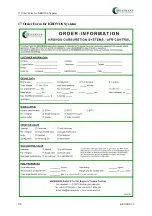
Page 104: ...17 Order Form for KRONOS Systems 96 KRONOS 20 17 Order Form for KRONOS Systems...


