6 Electric Connection
34
KRONOS 20
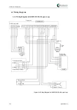
6.1.3
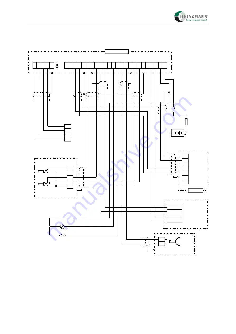
Wiring Diagram for KRONOS 20 with
λ
-Sensor Signal
1 2 3 4 5 6 7 8 9 10 11 12 13 14 15 16 17
18 19 20 21
12/24 V
2
1
5
6
KRONOS 20
E-LES
Electronically
controlled MAS
Battery
Fuse
6 A
Governor
on
Control Unit
Engine Stop
Summenalarm
3
4
7
3
2
4
1
Boost Pressure Sensor
Temperature Sensor
A
B
Magnetic Pickup IA ..
Lambda-Signal
5
4
2 3
T x D
R x D
24V
0V
Connection to
Programmer
or PC
1
SUB-D plug 9-pole
black +
grey -
T
H L
white
white
Heater for
Lambda-Sensor
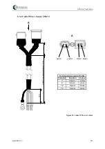
Figure 18: Wiring Diagram for KRONOS 20 with closed Loop and
λ
-Sensor Signal
Summary of Contents for E-LES 30
Page 2: ......
Page 8: ......
Page 104: ...17 Order Form for KRONOS Systems 96 KRONOS 20 17 Order Form for KRONOS Systems...

