10 Misfire Detection (optional)
50
KRONOS 20
Filtering of speed signals for misfire monitoring must always be done over two
crankshaft rotations.
To determine the thresholds for monitoring and error messages proceed as follows:
1.
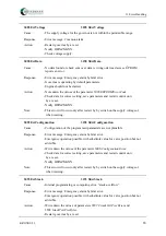
Using the identified value for (50
SpeedVarSampleSize
), run the engine to several load
points both under normal conditions and with selected cylinders switched-off. Two
different load-dependent curves for (2050
SpeedVariance
) result, one representing the
"good" and the other the "bad" operating conditions. Pay attention that the curves dif-
fer noticeably from each other at all chosen load points.
2.
Record the load value in (6000
MisfireWarn:P(x)
) and (6020
MisfireEcy:P(x)
). Draw
the warning characteristic and shutoff characteristic between the two limit characteris-
tics and record the respective values in (6010
MisfireWarn:nVar(x)
) and (6030
Mis-
fireEcy:nVar(x)
). Enable the functions (4055
MisfireWarnCurveOn
) and/or (4056
Mis-
fireEcyCurveOn
).
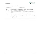
3.
Determine the delay times for (55
MisfireWarnDelay
) and (56
MisfireEcyDelay
). Only
when the current value of (2050
SpeedVariance
) has exceeded the warning and/or the
shutoff characteristic for at least the respective time indicated the errors (3046
ErrMis-
fireWarn
) / (3047
ErrMisfireEcy
) are triggered. When the value of (2050
SpeedVari-
ance
) falls below the load-dependent trigger level by relative 15 % the error (3046
ErrMisfireWarns
) is cleared. The emergency shutoff signal (3047
ErrMisfireEcy
) on
the other hand can be cleared only by a reset or by an error clearing through a commu-
nication module or switch function.
Note
Summary of Contents for E-LES 30
Page 2: ......
Page 8: ......
Page 104: ...17 Order Form for KRONOS Systems 96 KRONOS 20 17 Order Form for KRONOS Systems...

