background image


7 Technical data 

44


Positioner DC 6-06 

7.3.3


PWM setpoint, stop signal digital, actuator with disc rotor motor 


2 3 4 5 6 7 8 9 10 11 12 13 14 15 16 17

T

18

C
B

D

A
E

M

DC ... 6-06

StG 6 .. 40 - 01

Actuator

Fuse

12 A

Control

on

Control unit

Common alarm

Stop digital

22 23

24 25

CU-01

1

L

H

19 20 21

StG actual position

with Analogue signal

or PWM signal

0 V

analog/PWM

 PWM setpoint

Error reset

Supply voltage

12 V DC or 24 V DC

+

-

0 V

PWM


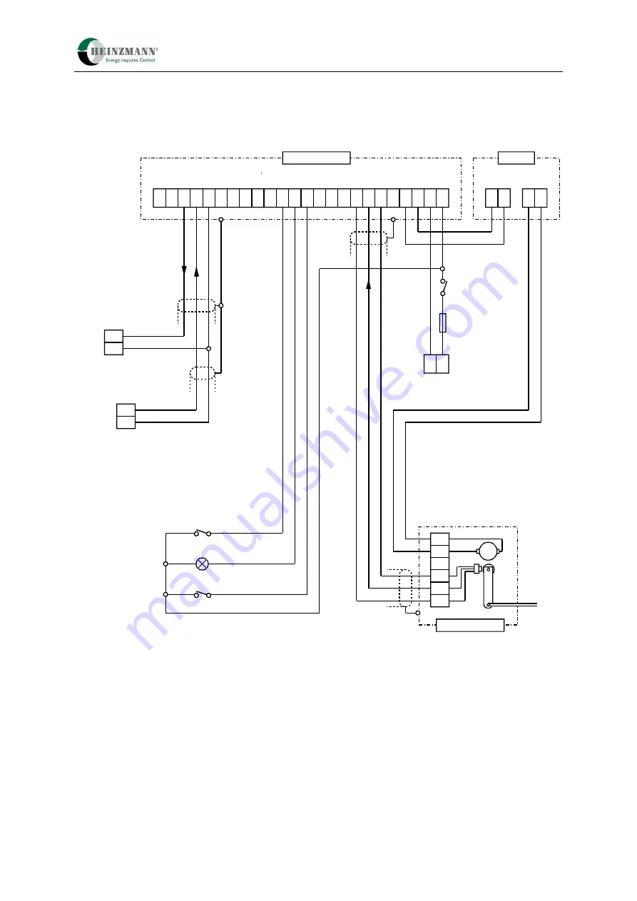
Fig. 4 Terminal connection diagram 3 – PWM setpoint, stop signal digital, actuator with disc rotor motor 

Summary of Contents for PANDAROS DC 6-06

Page 1: ...soever or passed on to any third parties Manual DG 08 001 e 10 08 Heinzmann GmbH Co KG Engine Turbine Management Am Haselbach 1 D 79677 Sch nau Germany Phone 49 7673 8208 0 Fax 49 7673 8208 188 E mail...

Page 2: ......

Page 3: ...s free from error complies with industrial standards or fulfils the requirements of any special application To avoid any injury to persons and damage to systems the following monitoring and protective...

Page 4: ...s HEINZMANN expressly rejects any implied guarantee pertaining to any marketability or suitability for a special purpose including in the event that HEINZMANN was notified of such a special purpose or...

Page 5: ...3 Parameterization of the HEINZMANN control units 15 3 1 Parameterization options 15 3 2 Saving the data 16 3 3 DcDesk 2000 16 3 4 Value range of parameters 17 3 5 Activating functions 18 3 6 Paramet...

Page 6: ...2 Error detection with the PWM inputs 36 6 4 Actuator position output with analogue output 36 6 4 1 Value range of the analogue output 36 6 5 Actuator position output with PWM output 37 6 5 1 Value ra...

Page 7: ...gram and Hand Programmer 57 10 Error handling 58 10 1 General 58 10 2 Error types 58 10 3 Error display 59 10 4 Error memory 59 10 4 1 Operating data memory and enhanced error memory 60 10 5 Bootloade...

Page 8: ...h could lead to fatal injury or severe injuries if it is not prevented CAUTION indicates a hazardous situation which could lead to minor injuries if it is not prevented NOTICE indicates possible mater...

Page 9: ...o requirements from the operating range of the system or motor 1 2 Safety measures for maintenance and servicing Before starting maintenance or repair work Block off access to the machine s working ar...

Page 10: ...mmunicates with the DcDesk 2000 parameterization and visualization tool or with a hand programmer across a serial interface 2 2 Firmware The control unit software is designed for universal use while p...

Page 11: ...pheral module with HZM CAN protocol DC 6 13 00 3 zz Speed and power dependent Gas positioner with misfire detection DC 6 15 00 4 zz Elektra gas measuring unit withgas flow control DC 6 16 00 5 zz Gas...

Page 12: ...sed representatives can access his own custom software If a customer wishes to protect an application against access by other HEINZMANN customers therefore he must ask HEINZMANN to create custom firmw...

Page 13: ...s 2 4 Conventions The following typographical conventions are used in this brochure 1911 ServoGain Parameter names are always shown in italics No distinction is made between the four 2 5 Parameter Lis...

Page 14: ...may be absent from special applications if they are not relevant for them In this case the parameter that belongs to an absent function will also be omitted Custom applications can contain new or enha...

Page 15: ...ameter Description The maximum possible level i e the choice number of parameters which can be accessed is determined by the diagnostic tester that is used and cannot be changed It is possible however...

Page 16: ...Output stage Actuator Position feedback Actuator reference values Output reference values Actuator limits Control value limiting Target actual value comparison Test mode setpoint selection Actuator po...

Page 17: ...ine during final inspection at the factory Parameterization with the hand programmer Complete parameterization can be carried out with the hand programmer PG 02 or HP 03 depending on the level This ha...

Page 18: ...000 also allows the user to print off screen displays and data recordings The data are stored in a standard text format for the purposes of further processing importing into reports etc The data recor...

Page 19: ...n Chapter 11 Parameter Description The value range of the parameters is also displayed by the PC or hand programmer 3 1 Parameterization options Some parameters have a value range that can have only t...

Page 20: ...e taken as examples Sensible settings which are appropriate for the specific application should therefore be used when setting a function 3 7 Resetting a control unit A reset involves resetting and re...

Page 21: ...de by parameter 4330 FuelSetpPWMOrAnalog One of the following values must be entered in it Channel type Setpoint source 0 Analogue signal current or voltage 1 PWM signal Table 5 Setpoint sources 4 1 1...

Page 22: ...ogue gearless actuator 4 2 Determining the actuator setpoint The setpoint generator connected to an analogue or PWM input determines the value of parameter 2350 FuelSetpoint This parameter always has...

Page 23: ...the index increases Inverting filling setpoint over this path is not permitted This parameterization is checked by the control unit and in case of error the configuration error 3000 ConfigurationErro...

Page 24: ...the 5 s stop request a 4Q actuator is positioned by force onto the lower limit stop whereas without a stop request and with a setpoint selection of 0 it is controlled to the lower limit stop 2Q actuat...

Page 25: ...ecuted as high active or low active by the software High active means that the stop request is only active when the signal 1 Low active means that the stop request is activated when the signal 0 The d...

Page 26: ...Voltage input 0 5 V 5510 AnaStopCurrOrVolt 2 Current input 0 22 mA It should be remembered that only a part of the range can be used for the signal e g 4 20 mA so as to be able to define error limits...

Page 27: ...tpSubstOrLast 1 continue working with 331 FuelSetpSubst 4332 FuelSetpHoldOrReset 0 when the measured value is back within the permitted limits reset the error and continue with the new valid value 433...

Page 28: ...asured value of the analogue stop signal 3511 AnaStop_Value exceeds or falls below the specified error limits 1512 AnaStop_ErrorLow and 1513 AnaStop_ErrorHigh 6 2 3 Error detection with the analogue i...

Page 29: ...in the ongoing test of the program memory 3078 ErrRAMTest Error in the ongoing test of the RAM memory 3081 Err5V_Ref Error at voltage reference values 3085 ErrVoltage Operating voltage too high or to...

Page 30: ...lculation time which the running program needs can be taken from the displayed value 3865 CalculationTime The value 3870 Timer is a rolling millisecond display that is used internally for time control...

Page 31: ...5 System monitoring Positioner DC 6 06 29 is being used can actually execute the function is indicated in 3601 LowPowerEnabled...

Page 32: ...stinction is made between external switches digital inputs and internal switch functions This means that although the system control is determined by the current value of switch functions the actual c...

Page 33: ...tion always has a value of 0 and is therefore always inactive A maximum of two digital inputs are available in the PANDAROS DC 6 06 Input 4 on terminal 9 and input 5 on terminal 11 Consequently a maxi...

Page 34: ...ut 1 must always be used because it is permanently assigned by the system Inputs Use Name Terminal Range Analogue input 1 Analogue stop request P1 2 3 6 0 5 V or 0 22 mA Analogue input 3 Analogue setp...

Page 35: ...or 1534 FuelSetAna_Filter A filter value between 1 and 255 is entered in these parameters A value of 1 means no filtering The following formula applies 5 62 _ value Filter s A filter value of 8 must b...

Page 36: ...ange below a measured value of 2 5 mA and above 21 5 mA is defined as inadmissible by the following parameters Number Parameter Value Unit 1530 FuelSetAna_Ref_0 20 mA 1531 FuelSetAna_Ref_100 4 mA 1532...

Page 37: ...elSetpPWMIn3 show the PWM ratio as a percentage and the measured value parameters 3501 FuelSetpFrequencyIn1 or 3505 FuelSetpFrequencyIn3 show the PWM frequency The selection as a PWM setpoint is made...

Page 38: ...he interrupt load on the control unit The PWM ratio is outside the error limits which correspond to half the lower reference parameter parameter from 1500 FuelSetPWMIn1RefLow or the mean between the u...

Page 39: ...MOutFrequency 6 6 Common alarm via alarm output The port on Pin 10 to which the signal 3801 CommonAlarm is automatically assigned is used for error display This common alarm is always active when at l...

Page 40: ...then 5103 CommonAlarmResetBoth must also be set The common alarm output will now be reset for 500 ms with each cleared error 6 7 Auto adjust with pushbutton At the left hand edge of the control unit...

Page 41: ...condensing Vibration resistance max 1 75 mm at 10 to 21 Hz max 0 24 m s at 21 to 45 Hz max 7 g at 45 to 400 Hz Shock 30 g 11 ms half sine Degree of protection IP 20 Insulation resistance 1 M at 48 V...

Page 42: ...put U 0 5 V Re 100 k fg 15 Hz or I 4 20 mA Re 200 fg 15 Hz Pin 10 Error lamp digital output Isink 0 3 A ground switching Pin 11 Stop digital input U0 1 V U1 5 V Rpd 100 k optional Rpu pd 4 75 k or Set...

Page 43: ...equest The stop signal can be selected digitally or analoguely by a current or voltage signal Digital inputs are not monitored for errors and must not be used for safety related functions as defined b...

Page 44: ...unit Common alarm Stop digital 22 23 24 25 CU 01 k max min Setpoint potentiometer cw out ccw or setpoint with voltage signal or setpoint with current signal 0 V 4 20 mA 0 V 0 5 V 1 L H 19 20 21 StG ac...

Page 45: ...with current signal 0 V 4 20 mA 0 V 0 5 V 1 L H 19 20 21 StG actual position with analogue signal or PWM signal 0 V analog PWM Stop analogue Error reset Supply voltage 12 V DC or 24 V DC C B D A E M...

Page 46: ...E M DC 6 06 StG 6 40 01 Actuator Fuse 12 A Control on Control unit Common alarm Stop digital 22 23 24 25 CU 01 1 L H 19 20 21 StG actual position with Analogue signal or PWM signal 0 V analog PWM PWM...

Page 47: ...position with analogue signal or PWM signal 0 V analog PWM PWM setpoint Error reset Supply voltage 12 V DC oder 24 V DC 0 V PWM C B D A E M StG 2 StG 2 DP LA Bosch EDC Actuator 2 1 3 4 5 2 1 5 4 3 7 2...

Page 48: ...M DC 6 06 StG 6 40 01 Actuator Fuse 12 A Control on Control unit Common alarm 22 23 24 25 CU 01 1 L H 19 20 21 StG actual position with analogue signal or PWM signal 0 V analog PWM Stop analogue Erro...

Page 49: ...analogue signal or PWM signal 0 V analog PWM Stop analogue Error reset Supply voltage 12 V DC or 24 V DC PWM setpoint 0 V PWM C B D A E M StG 2 StG 2 DP LA Bosch EDC Actuator 2 1 3 4 5 2 1 5 4 3 7 2...

Page 50: ...the evaluation of the feedback must be inverted small feedback signal with a large filling and vice versa The actuator is activated with the parameter 5910 ActuatorOn The operation of the amplifier i...

Page 51: ...on in all cases Only if the actuator is calibrated to its full stroke can exact positioning be expected subsequently The greater the difference between the measured values at the 0 and the 100 positio...

Page 52: ...without fail Automatic actuator calibration cannot be started if a fatal error is present or a setpoint not equal to 0 is selected With automatic calibration the control unit measures the reference v...

Page 53: ...way 8 1 3 Error detection from the feedback Similarly to sensors at analogue inputs the feedback has error limits by which the control unit can detect when a measured value is prohibited The error lim...

Page 54: ...nonlinear linkages or throttles or if the actuator is mounted directly without any linkage 4 2 Determining the actuator setpoint 8 3 1 Servo control loop The task of the servo or position control loo...

Page 55: ...The maximum current can be tolerated briefly for position changes but over longer periods the current has to be reduced to prevent the actuator being thermally overloaded This is why the servo control...

Page 56: ...is automatically deactivated off after a control unit reset The test mode is activated with parameter 5700 ActuatorTestOn 1 If an actuator setpoint is now selected with parameter 1700 ActuatorTestSet...

Page 57: ...ng and adjusted if necessary Owing to vibration the friction moment may be significantly less and other parameter settings than in a static system may be required In extreme cases this can even result...

Page 58: ...one particular hardware type 3840 HardwareVersion Version number of the control unit hardware 3841 AddHardwareVersion Version number for hardware modification 3842 SoftwareVersion Version number of th...

Page 59: ...ameters has its own identification number which is sent to the control unit The current identification number of the PC program or hand programmer appears in parameter 3850 Identifier The identificati...

Page 60: ...nternal computing errors of the control unit These errors can be due to faulty components or other unacceptable operating conditions They do not occur in normal circumstances The different errors can...

Page 61: ...urrent errors However the unit has an integral permanent error memory that provides an overview of errors that have occurred Every error that has occurred at least once is stored in this error memory...

Page 62: ...number of environmental data is set by the firmware that is used and cannot be changed However the choice of environmental data can be freely parameterized by the user with DcDesk 2000 The error count...

Page 63: ...he internal processor RAM memory and read back again If at least one cell does not contain the expected code the bootloader program enters an endless loop and the said display stays on Bootloader Prog...

Page 64: ...gurationError which tells you about the type of error The display of 3000 ConfigurationError changes every second and shows all existing configuration errors The communication program DcDesk 2000 disp...

Page 65: ...ergencyAlarm These errors are described in detail in Chapter 10 8 Error parameter list Error Cause 3050 ErrFeedback Error in the actuator feedback 3056 ErrFeedbackRef Error in the actuator feedback re...

Page 66: ...r Cause Configuration error Reaction Display Action Check the control unit configuration and rectify save parameters and perform a control unit reset Reference 10 6 Configuration error 3005 ErrAnaStop...

Page 67: ...second This situation exists when the injector pump the throttle the linkage or the actuator sticks or is not connected Reaction Error message The error clears when the difference is below 10 again A...

Page 68: ...rror limits 1952 FeedbackErrorLow 0 1953 FeedbackErrorHigh 65535 1956 FeedbackRefErrLow 0 1957 FeedBackRefErrHigh 65535 for the feedback save the settings Restart control unit and repeat the automatic...

Page 69: ...Action Restart control unit with 3 7 Resetting a control unit Notify HEINZMANN 3078 ErrRAMTest 3178 SErrRAMTest Cause The continuous monitoring of the main memory RAM returned an error Reaction Syste...

Page 70: ...unit cannot be operated Action Restart control unit with 3 7 Resetting a control unit Notify HEINZMANN Reference 10 5 Bootloader Note This error can only be seen in the bootloader 3089 ErrWatchdog Ca...

Page 71: ...art is possible 5 Parameter memory in the E2 PROM is invalid standard parameters of the firmware are transferred start is not possible 6 Exception memory in the E2 PROM is invalid start is possible Ac...

Page 72: ...98 IStackTestFreeBytes Notify HEINZMANN Restart control unit with 3 7 Resetting a control unit 3094ErrIntern 3194 SErrIntern 3195 SExceptionNumber 3196 SExceptionAddrHigh 3197 SExceptionAddrLow 3198 S...

Page 73: ...level is no higher than the level of the tool Parameters that require a save and control unit reset after a change are identified by RESET Only the first field parameter is given for curves and contr...

Page 74: ...e lower threshold for the stop request via analogue input 341 AnaStopThresholdHigh Level 6 Range 0 100 Page s 24 Definition of the upper threshold for the stop request via analogue input 342 AnaStopSe...

Page 75: ...elSetPWMIn3_Filter Level 4 Range 1 255 Page s 35 Filter for PWM input 3 for setpoint selection 1510 AnaStop_Ref_0 Level 4 Range 0 5V or 0 22 mA Page s 32 0 reference value of the analogue input for th...

Page 76: ...put for the setpoint selection 1534 FuelSetAna_Filter Level 4 Range 1 255 Page s 33 Filter value of the analogue input for the setpoint selection 1601 PWMOut_RefLow Level 4 Range 0 100 Page s 37 Minim...

Page 77: ...13 User level Maximum level of the dongle or hand programmer can be reduced 1876 ValueStep for hand programmers only Level 2 Range 0 65535 Increment for value changes 1900 FeedbackAdjustTime Level 6 R...

Page 78: ...ximum current for the actuator during motion 1918 ServoCurrentRed Level 6 Range 0 12 5 A Page s 53 Reduced current for the static state of the actuator 1919 ServoCurrentAdjust Level 6 Range 0 12 5 A P...

Page 79: ...4 Range 0 65535 Page s 50 Reference value for the reference coil RESET 1956 FeedbackRefErrLow Level 4 Range 0 65535 Page s 51 65 Lower error value for the reference coil 1957 FeedbackRefErrHigh Level...

Page 80: ...alogue input 2810 SwitchStopRequest Level 1 Range 0 1 Page s 23 State of the stop request via digital input 2828 SwitchErrorReset Level 1 Range 0 1 Page s 31 58 State of the switch function Error rese...

Page 81: ...cessive difference between control path setpoint and actual value 3056 ErrFeedbackRef Level 1 Range 0 1 Page s 63 65 Error in the reference value of the actuator feedback 3059 ErrFeedbackAdjust Level...

Page 82: ...vel 1 Range 0 1 Page s 27 61 68 Error display of the data record displayed in the bootloader 3090 ErrData Level 1 Range 0 1 Page s 27 63 68 Error display of the data record 3092 ErrConfiguration Level...

Page 83: ...quency at PWM input 3 for setpoint selection 3510 AnaStop_Percent Level 1 Range 0 100 Page s 32 Scaled value of the analogue input for the stop request 3511 AnaStop_Value Level 1 Range 0 5 V or 0 22 m...

Page 84: ...r externally present stop 1 stop request is active 3803 SystemStopped Level 1 Range 0 1 Page s 22 1 shows that the system is stopped 3830 Phase Level 1 Range 0 9 Page s 22 Current phase of the system...

Page 85: ...nge 0 65535 Page s 57 Identification number of the PC program hand programmer of the last stored parameter change 3865 CalculationTime Level 1 Range 0 16 384 ms Page s 28 Necessary calculation time of...

Page 86: ...parameters of the servo loop 3916 ServoCurrentSetpoint Level 1 Range 12 5 12 5 A Page s 53 Setpoint for the current through the actuator 3950 Feedback Level 1 Range 0 65535 Page s 49 Unscaled value o...

Page 87: ...or retained RESET 4335 ActPosOutPWMOrAnalog Level 4 Range 0 1 Page s 36 Configuration of the output channel type for the display of the current actuator position 0 analogue 1 PWM RESET 4340 AnaStopReq...

Page 88: ...02 CommonAlarmResetOn Level 2 Range 0 1 Page s 37 59 Selects whether the common alarm display will be briefly reset edge change when a new error is added 5103 CommonAlarmResetBoth Level 2 Range 0 1 Pa...

Page 89: ...0 4 quadrant energizing in both directions 1 2 quadrant energizing in direction 100 RESET 5920 ServoCurrentPCOn Level 6 Range 0 1 Page s Activates the actuator test mode to output the current from 192...

Page 90: ...g 7300ff FuelToActSp f x Position curve Level 6 Range 0 100 Page s 20 Filling values for the filling dependent actuator position curve RESET 7315ff FuelToActSp Pos x Level 6 Range 0 100 Page s 20 Posi...

Page 91: ...d or analogue gearless actuator 43 Fig 4 Terminal connection diagram 3 PWM setpoint stop signal digital actuator with disc rotor motor 44 Fig 5 Terminal connection diagram 4 PWM setpoint stop signal d...

Page 92: ...19 Table 6 Setpoint type 19 Table 7 Digital Inputs 30 Table 8 Switch functions 31 Table 9 Switch function assignment 31 Table 10 Analogue inputs 32 Table 11 PWM Inputs 35 Table 12 Analogue output 36...

Page 93: ...ommon alarm 55 Configuration PWM inputs 31 Control unit Reset 14 Control Unit Identification 52 Serial number 52 Conventions 7 Current errors 55 Data Management 52 Data saving 12 DcDesk 2000 7 12 Digi...

Page 94: ...meterization DcDesk 2000 11 End of line 11 EOL 11 Hand programmer 11 Presetting 11 Parameters 8 Control map list 84 Curve list 84 Function list 81 Measured value list 74 Overview table 67 Parameter li...

Page 95: ...r DC 6 06 93 Versions 5 Stack depth Monitoring 24 Switch functions Motor stop 19 Switch Functions Allocation 27 System description 4 Technical data 35 PANDAROS 35 Value range 13 Voltage references Mon...

Page 96: ...selbach 1 D 79677 Sch nau Germany Please include the following information your name name and address of your company e mail or address where you want the manuals to be sent to if different from above...

Reviews: