7 Technical data
Positioner DC 6-06
47
7.3.6
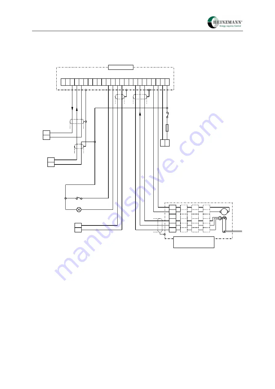
PWM setpoint, stop signal analogue, gearless actuator
2 3 4 5 6 7 8 9 10 11 12 13 14 15 16 17
T
18
DC ... 6-06
Fuse
12 A
Control
on
Control unit
Common alarm
1
L
H
19 20 21
StG actual position
with analogue signal
or PWM signal
0 V
analog/PWM
Stop analogue
Error reset
Supply voltage
12 V DC or 24 V DC
+
-
PWM setpoint
0 V
PWM
C
B
D
A
E
M
StG 2..., StG 2...DP,
LA .., Bosch EDC
Actuator
2
1
3
4
5
2
1
5
4
3
7
2
1
5
6
S
tG
w
ith
C
ann
on
pl
ug
S
tG
2
010
.. 2
080
.. S
V
S
tG
2
040
D
P
St
G wit
h t
er
m
in
a
l
St
G
20
1
0..
80
KV
S
tG
w
ith
AM
P p
lu
g
S
tG
2
005
-10
, S
tG
200
5D
P
LA
25
..3
5
Bo
sc
h
ED
C
Fig. 7 Terminal connection diagram 4
– PWM setpoint, stop signal analogue, gearless actuator
Summary of Contents for PANDAROS DC 6-06
Page 2: ......


