8 Actuator and feedback
Positioner DC 6-06
53
The normal parameters are used outside the double range. Between these two values,
interpolation is used to achieve a smooth transition. This function is always active. A
value of 100 % means no influence on the servo loop parameters. The current correction
factor is displayed in the parameter 3905
ServoPIDCorr
.
The values for the servo loop vary depending on the actuator type and must be set
accordingly. The initial settings are made at the factory by HEINZMANN when the
control unit is shipped and do not normally need to be altered.
8.3.2
Actuator current
The servo loop uses the servo loop parameters to calculate the current 3916
ServoCurrentSetpoint
for the actuator. To prevent the actuator from being overloaded, the
maximum current can be limited with parameter 1917
ServoCurrentMax
. The maximum
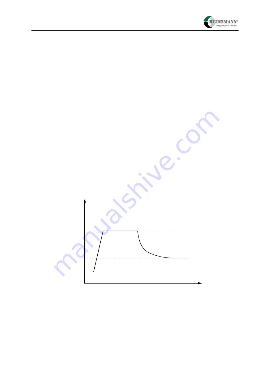
current can be tolerated briefly for position changes, but over longer periods the current has to
be reduced to prevent the actuator being thermally overloaded. This is why the servo
controller reduces the current under static load by an exponential function with a time
constant of approx. one minute to the value set with parameter
1918
ServoCurrentRed.
The reduction only begins after the delay time 1916
ServoCurrentRedDelay
. If this parameter does not exist, the reduction begins without a delay.
ZEIT [s]
STROM
[A]
Maximalstrom
<1917>
reduzierter Strom
<1918>
Fig. 8 Current reduction under static load
The maximum current is still available for dynamic position changes. When setting the
current reduction, the current must be measured in the supply cable to the actuators,
with the corresponding cable length. It must be remembered that the current cannot be
measured until the actuators have warmed up (static operation) because the flowing
current changes as temperature rises.
Current max.
<1917>
Reduced curent
<1918>
CURRENT
[A]
TIME [s]
Summary of Contents for PANDAROS DC 6-06
Page 2: ......


