9
Parameter Adj. Window
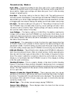
Gyro Gain
– The factory setting for the Gyro gain is 18. Lower settings will
make the FORM500 react more smoothly to the controls but the quad will not
be as stable. Higher gain settings will make the quad “hunt” while hovering
instead of remaining still.
Aux Gain
– The factory setting for the Aux Gain is 6.8. This setting does not
normally need to be adjusted. Lower settings will make the FORM500 oscillate
before settling in a hover. Higher settings will make the quad transition to a hover
with aggressive movements. Raising this setting could make videos more jumpy.
Alt. Gain
- The factory setting for Alt. gain is 15. This setting controls how much
the FORM500 rises and falls while hovering. Lower settings will allow more
movement and a smoother flight. Higher settings will reduce vertical motion,
but can also make videos more jumpy.
Low Voltage
– The factory setting is 10.8V. When the battery reaches the
voltage in this window and the FORM500 is in the Position Hold mode, it will
climb to 20 meters and return to home. If the FORM500 is flown a long distance
while heavily loaded, this value should be increased so the battery does not
die before the quad lands.
Land Speed
– This parameter controls how fast the quad descends when
in Position Hold or is in a Return to Home routine. The factory setting for this
adjustment is MED. The HIGH setting could be used if the quad is heavily loaded.
The LOW setting is best used when FORM500 is not carrying any accessories.
Attitude Window
– This artificial horizon displays the FORM500’s attitude for
both the roll and the pitch axis. When on a level surface, the line separating the
blue sky and the brown ground should be in the middle of the green horizon
lines. The sensor calibration procedure should be performed any time the
display is not centered when the FORM500 is level or if the display is drifting
while the quad is stationary.
Heading Window
– This is a graphic display of the data from the Heading
Sensor in the Sensor Data window. Magnetic interference from computers,
other electronic devices and metallic structures can affect the accuracy of this
sensor. The best results from this sensor will be obtained when the FORM500
is in an open area.
Remote Controller Signal Window
– These displays show the current
positions of the left and right sticks and the two switches that control the flight
functions. The pulse width for each channel is also displayed. The values should
be between 1000 and 2000. If lower values are seen on the throttle channel,
center the throttle trim.
Model Type
– This window should always display FORM500.
Sensor Data Window
– These displays show live data from the various
sensors on the FORM500.
Summary of Contents for FORM500
Page 17: ...17 ...
Page 20: ... HMXE0863 ...


