3
SETUP
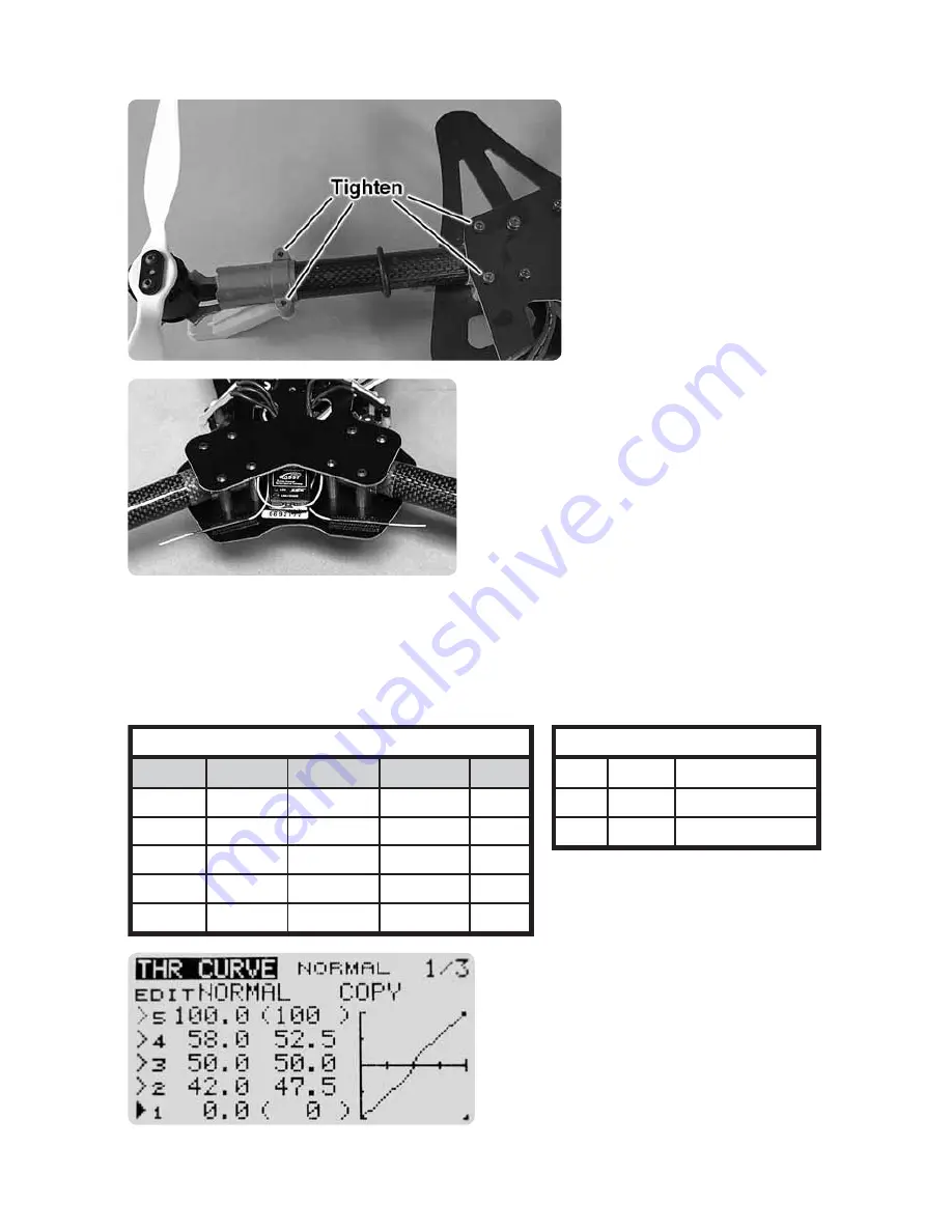
The Voltage 500 3D does
not need any assembly. All
the non-adjustable bolts
have been set to the proper
torque and have thread
locking compound applied
to keep them secure. The
tension of bolts that clamp
the booms should be
checked before each flight
by twisting each motor
mount. If the boom is not
tight, these bolts should be
tightened.
Your transmitter should have at least 5
channels with a 3 position switch for
channel 5. Channel 5 is used to disarm
the motors and select the 3D or stability
flight modes. The setup below is typical
for most Futaba and Tactic transmitters.
Most Spektrum radios can use a similar setup by using the channel name and
not reversing the throttle channel. A small receiver can be mounted on the top
plate and still fit below the canopy. We recommend mounting the receiver at
the back of the frame between the rear tube holders.
CHANNEL ASSIGNMENTS
MODEL TYPE: Airplane
Channel
Aileron
Elevator
Throttle
Rudder
Gear
Direction
normal
normal
reverse
normal
normal
Dual Rates
80/100
80/100
80/100
Expo
-30/0
-30/0
-30/0
End Points
100/100
100/100
100/100
100/100
100/100
SWITCH ASSIGNMENTS - Ch 5
Gear
Gear
Gear
-100 %
0 %
+100 %
Motors Disarmed
3D mode
Attitude mode
Make sure that your throttle curve is
linear. The motor’s transition time from
forward to reverse can be reduced
by setting points a few % above and
below midstick, making the throttle
curve as steep as possible between
those points.


