12
01
Storage tank
01A+B
Storage tank’s suspension point (used only in production process,
ignore them
)
01C
Handles
02
Filling pipe (for the closed circuit)
02A
Safety valve 3 BAR
03
Elbow raccord (4 pcs)
04
Thermal fluid inlet pipe (to the storage tank from the collector) (indi
-
cation “jacket”)
05
Small connection tube
05A
Insulated cover of the small connection tube
06
Raccord
07
Water-tight compression ring
(4 pcs).
08
Hot water outlet pipe
for home consumption
(indication: “hot outlet”)
09
Magnesium rod
09A
Magnesium rod socket
09B
Magnesium rod’s plug (ó”)
10
Thermal fluid outlet pipe
(from the collector to the
storage tank)
11
Collector(s)
12
Pipe unions (collector connectors). Only for models
with two collectors
13
Bottom left hand collector pipe
13A
Plug 1/2”
14
Filling pipe for the closed circuit
14A
Plug 1/2”
15
Cold water inlet pipe
(indication: “cold inlet”)
15A
Reducer (3/4” – 1/2”)
16
Thermal fluid outlet pipe (from
the storage tank to the collec
-
tor) (Indication: “jacket”)
17
Top right hand collector
pipe
17A
Plug 1/2”
18
Large connection
tube with insula
-
tion cover
19
Thermal fluid
inlet pipe
(return to the
collector)
20
Protective side
cover
20A
Face plate
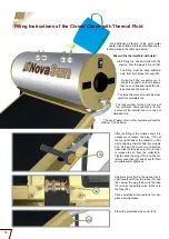
Analytical description of the storage
tank’s and collector’s components
01
02A
02
03 04
05 06
07
07
05A
12
13A 13
10 11
03
07
05A
09A
09
09B
19
03 04
07
08


