03
18
16
15 15A
03
03
07
05
08
04
10
17
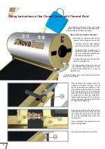
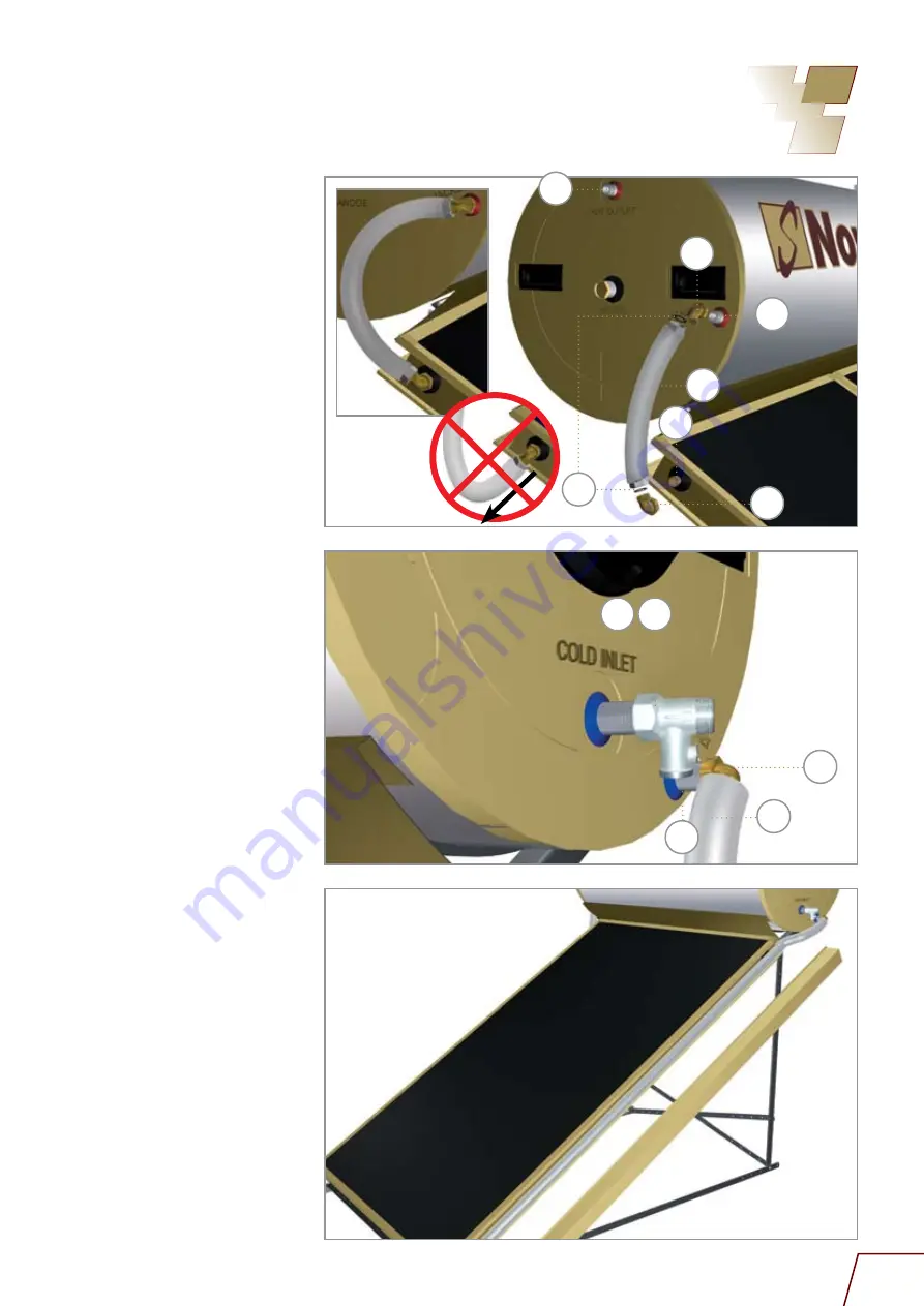
Connection instructions of the storage tank, collector and
components
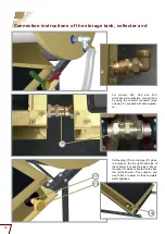
Screw the elbow raccords (03) on the
pipes of the storage tank (04) and (16)
with the indication “jacket” and on the
pipes of the collector(s) (10) and (19)
respectively.
Afterwards join the small connection
tube (05) onto (04) and (10) and the big
connection tube (18) onto (16) and (19)
respectively.
Before connecting the
tubes (05) and (18) ensure that the
compression rings (07) have been
placed on the tubes.
Screw the non-return valve (15B) on the
inlet pipe (15) of the storage tank (indica
-
tion: “cold inlet”).
For models 200, 260 and 300, use
the reducer 3/4”-1/2” (15A). Screw the
spherical switch (15C) on the non-return
valve.
note
In cases that you use the valve type
(15BC), use the appropriate for each
case procedure.
Connect the cold water supply to the
spherical switch and turn the cold water
supply on until the storage tank is com
-
pletely filled. When you are filling the
storage tank with water, the outlet of hot
water (08) should be opened. Connect
the hot water supply to the storage tank
outlet pipe (08). (Indication: “hot outlet”).
After connecting all the fittings, check
very carefully all connections for their
complete water tightness.
attention
In regions where the temperature falls
bellow zero, ensure that the connection
tubes of the storage tank and collector
as well as the hot and cold water piping
to/from the solar water heater are well
insulated.
FOLLOW STEP BY STEP THE
INSTALLATION INSTRUCTIONS OF
THIS MANUAL.
ALL THE PLUMBING INSTALLATIONS
MUST BE MADE IN ACCORDANCE
WITH THE PLUMBING REGULATIONS
APPLICABLE IN YOUR AREA.


