Components
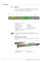
Reset button
Reset button for a manual reset of the system. See
on page 79.
System Status LED
The LED (light-emitting diode) indicates the system status by using the
following symbols and colors:
Symbol
Color
Description
Red
Critical system status: one of the
installed modules is in error status.
Yellow
System is still in operating, but
requires attention e. g., warning or
maintenance.
Green
No unit in error or warning status
Table 3-1 LED display
Liquid Crystal Display
The Liquid Crystal Display (LCD) comprises 4 lines of 20 characters to
display menu functions, system information and events.
Control Keys
The control keys serve to navigate in the LCD menu. See
on page 31.
Fastening Hole
4 fastening holes to attach the Energy Manager to the rack
Main Fuse
Fuse to safeguard the power supply
Power Supply Port and LED
Port that supplies the power to the Energy Manager. The LED is green
when power is supplied. In case of incorrect polarity, it is red.
SD card holder and LED
Slot in which to insert SD memory card. The LED illuminates briefly each
time the SD card is accessed.
LAN Port
Port for RJ-45 LAN and Ethernet
RS232 Port
Non isolated RS232 interface
RS 485 Port
Non isolated RS485 interface
Modem LED
Light-emitting diode showing mode and status of the GPRS modem. The
LED illuminates briefly each time the modem is sending data.
16
Energy Manager 2.0 - Instruction Manual
Summary of Contents for Energy Manager 2.0
Page 1: ...Energy Manager 2 0 Instruction Manual ...
Page 6: ......
Page 14: ......
Page 78: ......
Page 93: ...Energy Manager 2 0 Instruction Manual 93 ...
Page 94: ......
Page 101: ...Heliocentris Industry GmbH Rudower Chaussee 29 12489 Berlin Germany http www heliocentris com ...


