Components
3.1.2
Back Side
The I/O Panel is attached to the Energy Manager with a 128-pin plug
connector. It provides ports for analog or digital inputs. All connecting
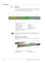
points on the back side are shown in Figure 3-2.
Figure 3-2 Energy Manager rear side
1
Digital input (8x)
2
Relay (8x)
3
Attachment screw right (2x)
4
Handle right
5
RS 232 port (isolated)
6
RS 485 port (isolated)
7
CAN bus port (isolated)
8
Cable guide
9
Grounding connection
10
Analog input single ended (9x)
11
Handle left
12
Attachment screw left (2x)
13
Input PT1000 temperature sensor (5x) 14
PWM port (2x)
15
Analog Input Battery differential
ended (5x)
TIP
The I/O Panel ports and PIN assignments are also printed on the cover of
the device in order to facilitate assignment when working from the device’s
front side.
Back Side Viewed from Above
The elements needed for proper and stable cable connections are shown
in Figure 3-3.
Figure 3-3 Energy Manager back side viewed from above
1
Handle (right and left)
2
Shielding clamp
3
Cable fastener (4x)
4
Screw for I/O Panel (4x)
18
Energy Manager 2.0 - Instruction Manual
Summary of Contents for Energy Manager 2.0
Page 1: ...Energy Manager 2 0 Instruction Manual ...
Page 6: ......
Page 14: ......
Page 78: ......
Page 93: ...Energy Manager 2 0 Instruction Manual 93 ...
Page 94: ......
Page 101: ...Heliocentris Industry GmbH Rudower Chaussee 29 12489 Berlin Germany http www heliocentris com ...


