Getting Started
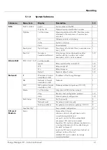
Contact
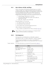
Value
Analog inputs:
Battery voltage 1 – 5
0 – 60 V
DC
+24 V
DC
max. 18 W
Table 4-1 Standard contact allocation
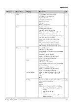
Depending on the installed modules, Heliocentris recommends a
. The assignments may vary
depending on the installed software and hardware components.
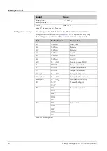
Port
Default sensor
Connection
AI1
0-20mA
Fuel1 level
AI2
0-20mA
Battery 1
AI3
0-20mA
Battery 2
AI4
0-20mA
Load 1
AI5
0-20mA
Load 2
AI6
0-20mA
Load 3
AI10
0 – 60 V
DC
Supply voltage EM2.0
T1
PT1000
Temperature shelter
T2
PT1000
Temperature outdoor
T3
PT1000
Temperature battery
Battery In 1
0 – 60 V
DC
Voltage battery string 1
Battery In 2
0 – 60 V
DC
Voltage battery string 2
Battery In 5
0 – 60 V
DC
Voltage starter battery
DI1
0<3V
1>3V
Genset RunSignal
REL1
NO
Genset 1 acc/start
GND
24V
COM
NC
REL4
NO
Aircon start
GND
24V
COM
NC
Table 4-2 Port assignment
Configuration example
28
Energy Manager 2.0 - Instruction Manual
Summary of Contents for Energy Manager 2.0
Page 1: ...Energy Manager 2 0 Instruction Manual ...
Page 6: ......
Page 14: ......
Page 78: ......
Page 93: ...Energy Manager 2 0 Instruction Manual 93 ...
Page 94: ......
Page 101: ...Heliocentris Industry GmbH Rudower Chaussee 29 12489 Berlin Germany http www heliocentris com ...


