background image

...PROTECTION MODES AND ERROR CODES CONTINUED

12

Item 4: Start Mode/Punch (Higher value is more aggressive):

The Reaktor ESC has 4 “punch” profiles that allow you to tune the initial power output of the ESC to suit your driving, ve-

hicle, and the surface. You will typically want a lower punch setting when the surface has less traction. To get the optimal 

performance out of LiPo batteries, on high traction sufaces, setting 4 is recommended. 

1.  Level 1 (70%): This setting will provide the smoothest throttle feel and least wheel spin.

2.  Level 2 (80%)

3.  Level 3 (90%): This is the highest setting that should be used with high performance NiMH batteries such as those 

included with your vehicle. 

4.  Level 4 (100%): This setting is recommended for use with LiPo batteries only and allows you to get the maximum ac-

celeration from your power system. Choosing a setting higher than #3 for use with NiMH batteries will cause inconsist-

ent operation of your ESC, including possible momentary power loss.

Item 5: Maximum Brake Force:

The Reaktor ESC has 4 maximum brake force settings allwowing you to tune your brakes for different driving surfaces. 

This setting works in conjunction with the brake EPA setting on your transmitter which can still be used to fine tune the 

braking force, however this setting affects the initial brake force also. Since your vehicle is using a high performance 

brushless motor which has great braking efficiency already, we have reduced the setting to #3. On some surfaces you may 

still find this setting to be too high and find that under heavy braking with 4wd vehicles the rear tires may come off the 

ground. This is a very unstable situation and should be avoided at all costs. If this happnes, reduce the maximum braking 

force to a lower setting. If however you are unable to stop and the lack of deceleration is not due to wheel slipping, you 

can increase the braking force. 

WARNING: Be sure to check your maximum brake settings by driving from full throttle to full hard brake in an open area. 

If the rear tires come off the ground causing a front flip, the vehicle will tumble out of control and could cause personal or 

property damage.

1.  25%: This is the lowest setting and should only be used when driving with slow motors and on loose (low traction) 

surfaces.

2.  50%: It is not recommended to go below this setting on asphault surfaces as the stopping power may not be enough 

to safely slow your vehicle.

3.  75%: This is the default setting we feel will provide you the best starting point for many different levels of tration on 

various surfaces. Remember it is extremely important to only drive a vehicle as fast as you can safely stop it. If the 

vehicle hits something or someone it can cuase serious injury.

4.  100%: This setting is only recommended if you are running a slotted type motor, running this with a slotless style mo-

tor combined with a 4wd vehicle will likely cause front flips thus a loss of control of your vehicle.

Reset to Factory Defaults:

At any time when the throttle is located in neutral zone (except in the throttle calibration or programming mode), hold the 

“SET” key for over 3 seconds, the red LED and green LED will flash at the same time , which means each programmable 

item has be reset to its default value.

Audible/Visual Programming Alerts:

In dirty conditions or with various installations scenarios, visibility of the LED’s may be obstructed. To assist with setting 

the ESC parameters you will also be able to hear audible beeps from the motor that will indicate the value of flashes the 

LED is transmitting.

To help interpret the beeps and flashes we use a long time flash and long “Beep---” tone to represent number “5”, so it is 

easy to identify the higher quantity of flashes/beeps. This applies to both the programming parameter selection and also 

the value of each programmable item.

•  For example, if the LED flashes as the following:

 › “A long time flash” (Motor sounds “B---”)  =  the No. 5 item

 › “A long time flash + a short time flash” (Motor sounds “B---B”)  =  the No. 6 item

 › “A long time flash + 2 short times flash” (Motor sounds “B---BB”)  =  the No. 7 item

 › “A long time flash + 3 short times flash” (Motor sounds “B---BBB”)  =  the No. 8 item

 › “A long time flash + 4 short times flash” (Motor sounds “B---BBBB”)  =  the No. 9 item.


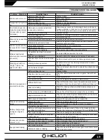
Use the table on the next page to better understand the programming process. This should help you navigate thorugh the  

programming menu.

Summary of Contents for Intrusion XLR HLNA0684

Page 1: ...ations are subject to change without notice Due to ongoing development the actual product may vary from images shown This product contains chemicals known to the State of California to cause cancer and birth defects or other reproductive harm This product is not a toy 14 Recommended for ages 14 and up Adult supervision required for ages under 18 years old Contains small parts keep out of reach of ...

Page 2: ...ry our best to ensure the information you need to introduce you to this form of product maintenance is available to you though this manual Please see the trouble shooting guide at the back of this manual for assistance in resolving issues either as they are experienced out of the box or as found after regular use Assuming your product functions properly as intended out of the box the best thing yo...

Page 3: ...harge a damaged battery Inspect the battery and charger before use Never use a battery or charger if the wire or connector has been damaged or if the battery has experienced a short Incorrect use of the battery connections or charging equipment can cause personal injury or property damage Never allow batteries or charger to come in contact with moisture at any time Stop charging immediately if the...

Page 4: ...an result from careless operation Please consult your local hobby dealer with any questions or troubleshooting issues And of course don t forget to have fun you deserve it after reading through all of these safety tips 1 Steering wheel controls left right motion designed to be operated with right hand 2 Throttle trigger controls forward reverse brake motion designed to be operated with left index ...

Page 5: ...PROCESS WITH THE VEHICLE S WHEELS OFF THE GROUND 1 With the transmitter in close proximity but not closer than 1ft to the receiver turn on the transmitter first then the vehicle The LED on the receiver will blink indicating that the receiver is not paired to a transmitter that is on 2 Turn the transmitter OFF hold the REV PAIR BIND button and turn the power back ON to put the transmitter into pair...

Page 6: ...onary when no throttle input is applied The channel reverse function reverses the direction of operation of the servos or ESC s relative to the transmitter steer ing and throttle inputs This function would be used if for example turning the transmitter steering wheel right resulted in the model turning left and vice versa Some ESC s require that the throttle channel be reversed in order to program...

Page 7: ...tes while the transmitter is on a slow beeping alarm will sound to indicate that there has been no action and the power should be turned off and back on to reset the transmitter alarm Low Battery Voltage Alarm If the transmitter battery voltage drops to 4 5V or less a slow beeping alarm sounds and the power LED light will blink Battery Replacement WARNING Do not attempt to charge non rechargeable ...

Page 8: ...direc tion using the throttle control can cause damage to your vehicle and electronics and will void the warranty Using your transmitter for the first time 1 Turn the transmitter ON and ensure the LED is lit SOLID and it is not giving an audible alarm indicating the batteries are supplying adequate voltage for proper operation 2 Ensure the battery in your vehicle is secured charged and plugged in ...

Page 9: ...on Throttle signal loss protection Motor blocked protection a Easily programmed with the SET button on the ESC or with the LED Program Card Your ESC has been pre installed at the factory but before using your vehicle each time it is good to double check the wir ing for damage or loose connections to ensure everything is in working order before use Refere to the diagram below to check the connectio...

Page 10: ... output power if the throttle signal is lost for 0 2 second Throttle range calibration Hold your transmitter approx 1ft away while setting 1 Turn Transmitter ON first transmitter should alwasy be on if ESC is ON 2 Ensure your Throttle channel Ch 2 on your transmitter is set to Reverse 3 Adjust both Throttle and Reverse Brake EPA settings to 100 4 With the ESC OFF press and hold the Set button near...

Page 11: ... from your ESC Motor Battery This setting should be chosen based on the number and type of cells you are using For LiPo batteries we recommend setting LVC to 5 using a setting lower than this may cause over discharge of some batteries and cause damage to your battery which could lead to a fire 1 No Protection ONLY to be used with NiMH or NiCd type batteries Since your vehicle comes equipped with a...

Page 12: ... vehicle will tumble out of control and could cause personal or property damage 1 25 This is the lowest setting and should only be used when driving with slow motors and on loose low traction surfaces 2 50 It is not recommended to go below this setting on asphault surfaces as the stopping power may not be enough to safely slow your vehicle 3 75 This is the default setting we feel will provide you ...

Page 13: ...rogrammable Items Blinks of GREEN LED Programmable Value Blinks of RED LED Black background default settings 1 2 3 4 5 6 7 8 1 Running Mode Forward with Brake Forward Reverse with Brake 2 Drag Brake Force 0 5 10 15 20 25 30 40 3 Low Voltage Cut Off Threshold No Protection 2 6V Cell 2 8V Cell 3 0V Cell 3 2V Cell 3 4V Cell 4 Start Mode Punch Higher value is more aggressive Level 1 70 Level 2 80 Leve...

Page 14: ... Battery voltage too low LVC active Charge or change batteries ESC over temp protection active Turn off ESC and allow ESC and motor to cool before running again Loss of throttle signal Check transmitter and receiver check wiring Random stopping or restart irregular opera tion Strong electro magnetic interference in the oeprating area Reset ESC or change operation location Car doesn t accelerate En...

Page 15: ...rom changing position in the battery tray Although great for first time users Helion RC products are indeed advanced radio controlled vehicles with sensitive elec tronics and moving parts capable of causing injury if used improperly Always use caution and common sense as failure to operate your Helion RC product in a safe and responsible manner can result in damage to the product or other properti...

Page 16: ... before the pinion gear moves this is purely by feel not visual Check this movement in multiple places by rotating the spur gear approximately 1 6 rotation and checking again iii If the spur gear is allowed to move more than a very small amount or if it there is no backlash the gear mesh must be adjusted If there is a lot of movement it is recommended to attempt to tighten the mesh Attempted adjus...

Page 17: ...ime between the tire and wheel Allow the glue to fully dry before operating your vehicle Caution Be sure to use extreme care when using hobby grade CA glue It is specially formulated to cure quickly and create a strong bond It will bond skin and can cause injury if used improperly Follow manufacturer s warnings and directions when using CA glue It is always recommended to wear eye protection when ...

Page 18: ...or wrapped around the spinning parts of the drivetrain Small objects like fish ing line for example can wrap around a drive shaft overheat and melt due to the friction and cause the entire drive train to lock up Although a big problem it can be difficult to see when inspecting Always remove the wheels from your vehicle when starting drivetrain related issues 4 The layout of components in your vehi...

Page 19: ...en screws if over tight Front wheels too tight Check and adjust wheel nuts to ensure the wheels are not too tight Vehicle top speed and acceleration is slow Battery voltage too low Charge battery Drivetrain has too much friction Check for debris excessive wear on gears inspect bear ings Gear mesh too tight Loosen gear mesh Pinion gear is loose Check and tighten set screw on motor pinion Differenti...

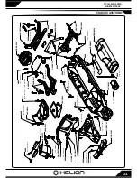
Page 20: ...mm HLNA0311 HLNA0310 bhcs M2 5x5mm fhcs M3x10mm HLNA0329 fhcs M3x12mm HLNA0307 locknut M3 HLNA0315 fhcs M3x12mm HLNA0645 HLNA0329 HLNA0329 HLNA0329 M3x13mm HLNA0352 HLNA0352 HLNA0349 HLNA0319 fhcs M3x14mm HLNA0319 HLNA0319 bhcs M3x6mm HLNA0329 fhcs M3x20mm HLNA0319 HLNA0398 fhcs M3x12mm HLNA0371 HLNA0319 fhcs M3x16mm HLNA0654 HLNA0314 HLNA0397 5x8x2 5mm HLNA0273 ...

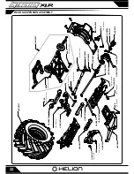
Page 21: ... HLNA0641 bhcs M3x12mm HLNA0644 HLNA0644 HLNA0640 HLNA0643 HLNA0644 HLNA0642 HLNA0641 HLNA0331 HLNA0139 HLNA0140 HLNA0646 locknut M3 bhcs M3x8mm bhcs M3x10mm bhcs M3x10mm bhcs M3x10mm bhcs M3x16mm bhcs M3x8mm bhcs M3x25mm bhcs M3x16mm bhcs M3x10mm shss M3x5mm HLNA0399 bhcs M3x12mm HLNA0642 RDNA0048 HLNA0252 bhcs M3x16mm KNNS003 bhcs M3x10mm HLNA0647 bhcs M3x12mm HLNA0399 ...

Page 22: ...286 bhcs M3x12mm HLNA0287 HLNA0326 bhcs M2 5x5mm HLNA0101 HLNA0344 HLNA0645 HLNA0650 locknut M3 HLNA0310 HLNA0326 HLNA0310 HLNA0387 HLNA0651 fhcs M3x20mm HLNA0331 bhcs M3x8mm HLNA0371 HLNA0422 HLNA0093 HLNA0313 HLNA0398 bhcs M3x16mm HLNS0655 bhcs M3x10mm fhcs M3x14mm fhcs M3x16mm fhcs M3x12mm bhcs M3x12mm ...

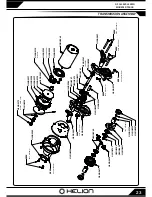
Page 23: ...M3X6mm HLNA0336 HLNA0286 bhcs M3x30mm HLNA0340 HLNA0342 bhcs M3x25mm HLNA0335 locknut M4x0 7mm HLNA0651 HLNA0651 HLNA0341 HLNA0286 HLNA0286 HLNA0413 HLNA0337 HLNA0412 HLNA0341 HLNA0372 1 5X8MM HLNA0341 HLNA0341 HLNA0338 HLNA0287 HLNA0332 HLNA0101 HLNA0101 M3x3mm HLNA0341 HLNA0356 HLNA0363 HLNA0338 HLNA0428 HLNA0411 HLNA0428 HLNA0337 HLNA0336 bhcs M3x6mm bhcs M3x4mm ...

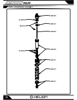
Page 24: ...24 FRONT REAR SHOCK ASSEMBLY HLNA0409 HLNA0408 HLNA0333 HLNA0332 HLNA0408 HLNA0331 HLNA0331 HLNA0332 HLNA0331 HLNA0410 ...

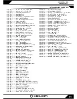
Page 25: ... HLNA0273 Tires Mounted Silver Wheels IMT HLNA0275 Wheels Silver IMT HLNA0276 Tires And Foam IMT HLNA0286 Bearings Rubber Sealed 5x10x4mm HLNA0287 Bearings Rubber Sealed 10x15x4mm HLNA0307 Bulkhead Set Front 10 ION HLNA0308 Camber Block Set F R 10 ION HLNA0313 Hub Set Rear 10 ION HLNA0314 Spindle And Carrier Set F 10 ION HLNA0315 Wheel Hex Set 12mm 10 ION HLNA0319 Steering Assembly Plastic 10 ION ...

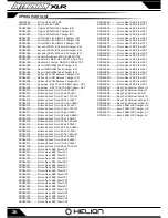
Page 26: ... Silicone Shock Fluid 60wt 800cSt RDNA0127 Silicone Shock Fluid 70wt 900cSt RDNA0128 Silicone Shock Fluid 80wt 1000cSt RDNA0212 Pinion Gear 48P Steel 12T RDNA0213 Pinion Gear 48P Steel 13T RDNA0214 Pinion Gear 48P Steel 14T RDNA0215 Pinion Gear 48P Steel 15T RDNA0216 Pinion Gear 48P Steel 16T RDNA0217 Pinion Gear 48P Steel 17T RDNA0218 Pinion Gear 48P Steel 18T RDNA0219 Pinion Gear 48P Steel 19T R...

Page 27: ...NOTES 27 1 10th SCALE 2WD MONSTER TRUCK ...

Page 28: ...000610 001 REV A HLNA0730 ...

Reviews: