


DE
15
Außenluft-Boxen – ALB EC
Montage- und Betriebsvorschrift
KAPITEL 8
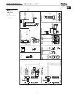
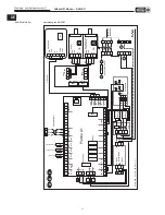
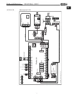
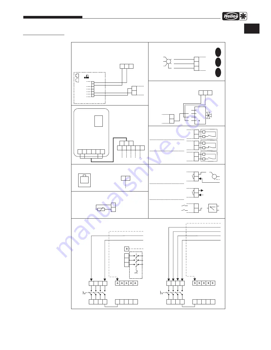
SCHALTPLÄNE
ALB EC /
Zubehörkomponenten
Anschlussplan SS-1251
■
Hauptsc
halter
■
W
asser
-
pumpe
■
Boost
Modus
■
Exter
-
ner
Sc
halter
■
Feuer
Notfall-
kontakt
■
A
ußenluft-
klappe
■
Hauptsc
halter
ALB EC 40/20
WW
:
3x1.5mm²,
1.1A,
230V~
ALB EC 50/30
WW
:
3x1.5mm²,
2.9A,
230V~
ALB EC 30/20 EH: 3 x 1.5mm²,
0.9A,
230V~
+ Elektr
oheizung:
ALB EC 60/35
WW
:
5x1.5mm²,
1.9A,
400V~
ALB EC 80/50
WW
:
5x1.5mm²,
2.9A,
400V~
N'
N'
N'
N'
N'
N'
N'
N'
N'
N'
CANH
CANL
■
Bedienteil
+12V
B
SD
A
GND
25
26
27
28
29
30
CANH
CANL
+12V
B
A
GND
(WHSH)
13
17
15
14
18
16
N
N
L
N
N
N
N
L3
L3
L2
L2
L1
L1
L1
L1
L1
L2
L2
PE
L
PE
PE
L
L
PE
■
P
otentialfrei
7
8
5
6
L2F
L1F
11
12
M
■
Betriebs-
meldung
V
entilato-
ren
N.C
max.
40m
250V~
max.
2A
A
C1
250V~
max.
2A
A
C1
max.
0.1A,
20V
A
max.
0.1A,
20V
A
L-open 230V~
■
Misc
her
ventil
24V~/ 0-10V=
~
~
+
0-10V
U
1
2
3
5
0-10V
GND
19
20
(WHSH)
KWL-CO
,
Ar
t.Nr
. 4272
2
KWL-FTF
,
Ar
t.Nr
. 4273
KWL-V
OC
,
Ar
t.Nr
. 4274
15-24V~
/ 24V=
A1
GND
~
~
+
-
A2
GND
EXT
■
Luftqualitätssensor
24V+
24V+
12V+
12V+
GND
GND
■
Ansc
hluss-
klemmen
■
Ansc
hluss-
klemmen
■
Ab
luftventilator
44
43
GND
0-10
CO2
+
85499 015 SS-1251 11.06.18 S
.1
32
33
31
GND
0-10
GND
0-10V
M
PE
N
L
max.
20m
max.
20m,
max.
10mA
RPM
RPM
■
Modb
us
25
26
B
RS485
A
TCP
■
T
emperatur
-
sensor Raum
56
55
Raum
GND
NTC 10k
D
S.1
E
F
S.2
S.3
Falls nic
ht g
en
utzt:
32-33 verbinden
L3
L3
■
Bauseits
zu stellen
Elektr
oheizung
ALB EC EH 30/20
4 x 1.5mm²,
9.5A,
400V~
Summary of Contents for ALB EC 30/20 EH
Page 23: ...21 Außenluft Boxen ALB EC Montage und Betriebsvorschrift DE ...
Page 45: ...21 Fresh Air Boxes ALB EC Installation and Operating Instructions EN ...
Page 46: ...22 Fresh Air Boxes ALB EC Installation and Operating Instructions ...
Page 47: ...23 Fresh Air Boxes ALB EC Installation and Operating Instructions ...


