


16
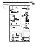
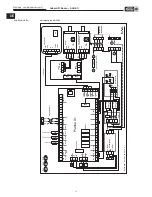
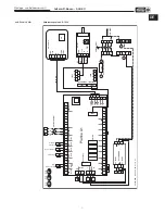
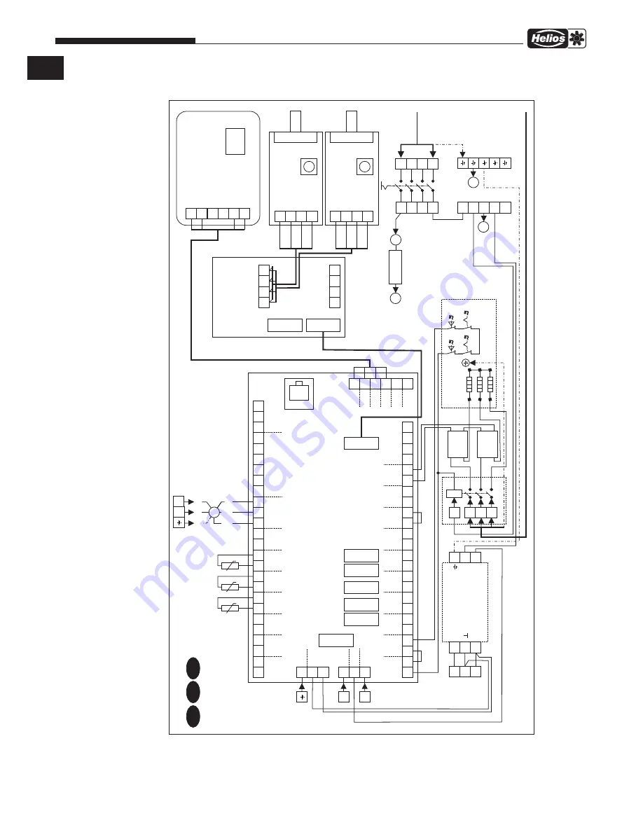
Außenluft-Boxen – ALB EC
Montage- und Betriebsvorschrift
Anschlussplan SS-1301
56
55
54
53
52
51
50
49
48
47
46
45
44
43
42
41
40
39
25
57
38
26
58
37
27
59
36
28
60
35
29
61
34
30
62
33
32
31
IN1
A
A
A
0
E
BCD
BCD
B
B
+12V
+12V
GND
GND
A
B
B
+12V
+12V
GND
GND
Room
IN2
1
1
5
2
6
2
I-B
US
I-B
US
CANH
CANH
CANL
CANL
I-BUS OUTPUT
+12V
+12V
B
B
SD
A
A
3
4
5
6
7
L-F
L
N
24V+
+
+
-
GND
GND
GND
GND
GND
GND
GND
GND
GND
GND
GND
GND
GND
GND
TK
0-10
8
9
10
11
12
13
14
15
16
17
18
19
20
21
22
23
24
PWM
RPM
PWM
W
A
T
-OUT
Ext3
Ext2
Ext1
CO2
PE DC12V
L
N
L
Fu
I-BUS
I-BUS
I-BUS
3.15A
T
SSR 40A
1
4-
3+
2
SSR 40A
1
4-
3+
2
3x2.3kW
A2
A1
N'
N'
LF
N'
L1'
Reset
115°C
115°C
50°C
50°C
Reset
20A
■
Filter
3x1.5mm²,
0.9A,
230V~
4x1.5mm²,
9.5A,
400V~
M
PE
N
L
N'
N'
N'
N'
L-F
12V+
N'
3
7
4
8
I-BUS INPUT
■
Bedienteil
■
V
olumenstr
om-
überwac
hung
RD
OR
■
Hauptsc
halter
L1'
L2'
L3'
N
L1F
L2F
LF
60
62
57
YE
BU
WH
V2 - 24VDC
HF30W
-DDR-A
V1 - 12VDC
B
U
B
U
GN
GN
OR
OR
WH/GN
WH/GN
NTC 10k
NTC 10k
NTC 10k
85499 064 SS-1301 05.06.18 S
.1
■
V
orheizung
■
Zuluftventilator
Grün Zuluft
Rot Vorheizung
Weiß A
ußenluft
■
Relais
■
Sic
herung
Platine A1
■
Sic
herung
V
entilator
10m 8p inkl.
0-10
RPM
D
S.1
E
F
S.2
S.3
ALB EC 30/20 EH
DE
Summary of Contents for ALB EC 30/20 EH
Page 23: ...21 Außenluft Boxen ALB EC Montage und Betriebsvorschrift DE ...
Page 45: ...21 Fresh Air Boxes ALB EC Installation and Operating Instructions EN ...
Page 46: ...22 Fresh Air Boxes ALB EC Installation and Operating Instructions ...
Page 47: ...23 Fresh Air Boxes ALB EC Installation and Operating Instructions ...


