


17
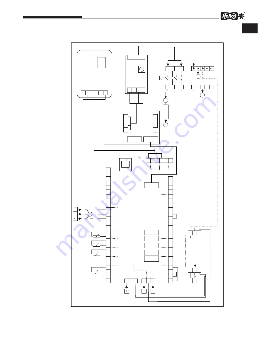
Fresh Air Boxes – ALB EC
Installation and Operating Instructions
Wiring diagram SS-1244
56
55
54
53
52
51
50
49
48
47
46
45
44
43
42
41
40
39
25
57
38
26
58
37
27
59
36
28
60
35
29
61
34
30
62
33
32
31
IN1
A
A
B
B
+12V
+12V
GND
GND
Room
IN2
1
1
5
2
6
2
I-B
US
I-B
US
CANH
CANH
CANL
CANL
I-BUS OUTPUT
+12V
+12V
B
B
SD
A
A
3
4
5
6
7
L-F
L
N
24V+
L1F
+
+
-
GND
GND
GND
GND
GND
GND
GND
GND
GND
GND
GND
GND
GND
0-10
8
9
10
11
12
13
14
15
16
17
18
19
20
21
22
23
24
PWM
RPM
W
AT
-OUT
Ext3
Ext2
Ext1
CO2
PE DC12V
L
N
L
Fu
L2F
FUSE
I-BUS
I-BUS
I-BUS
3.15A
T
RELAY
RELAY
RELAY
RELAY
RELAY
N'
L1'
3x1.5mm²,
1.1A,
230V~
LF
60
water outlet
(blue)
N'
N'
N'
N'
62
57
L-F
12V+
N'
3
7
4
8
I-BUS INPUT
GND
RPM
PWM
N'
LF
M
PE
NL
YE
BU
WH
■
Contr
ol panel
Main s
witc
h
■
Suppl
y fan
■
supply (green)
preheater (red)
outdoor air (blac
k)
Electronic board A1
Fuse f
or fan
■
L1'
L2'
L3'
N
V2 - 24VDC
HF30W
-DDR-A
V1 - 12VDC
10m 8p inc
l.
NTC 10k
NTC 10k
NTC 10k
NTC 10k
85499 008 SS-1244 05.01.18 S
.2
0-10
RPM
A
0
BCD
B
+12V
GND
Filter
■
GN
B
U
GN
OR
WH/GN
ALB EC 40/20 WW
EN
Summary of Contents for ALB EC 30/20 EH
Page 23: ...21 Außenluft Boxen ALB EC Montage und Betriebsvorschrift DE ...
Page 45: ...21 Fresh Air Boxes ALB EC Installation and Operating Instructions EN ...
Page 46: ...22 Fresh Air Boxes ALB EC Installation and Operating Instructions ...
Page 47: ...23 Fresh Air Boxes ALB EC Installation and Operating Instructions ...


