Temperature Control System WHS HE
Installation and Operating Instructions
16
EN
EN
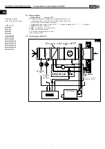
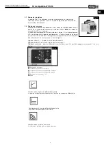
3�3 Assembly and function – WHSE
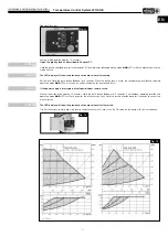
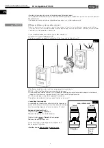
The electronic control unit WHSE is used as a supply air or room temperature controller in ventilation systems. The
control unit has a three-point-outlet for “colder” and “warmer”.
Assembly takes place on a DIN profile rail in a switch cabinet or a separate protective casing. The casing of the control
unit has a protection class of IP 20 and it can be used with an ambient temperature of 0° ... 50 °C.
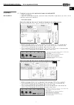
Function and assembly of the sensor
Der line cross-section should be at least 0.5 mm
2
. Shielded cables must be used for lengths over 25 m.
– Anti-freeze function
The anti-freeze temperature sensor (TFK)
must
be installed behind the warm water heater battery WHR.. (in flow direc-
tion), either as a mounted sensor in the heater battery, or as a contact sensor on the return line. If the temperature at the
anti-freeze sensor falls below 10 °C , the actuator opens the three-way-valve of the WHSH. The anti-freeze controller
works as a P-controller with a proportional range of 5 °C, i.e. at 5 °C at the anti-freeze sensor, the signal at terminal 6
goes to 24 V~. If the temperature at the anti-freeze sensor falls below 5 °C, the alarm relay will switch, and the alarm
LED (Pos.
ó
) will light up. The alarm signal can be reset with the reset button (Pos.
ó
).
The anti-freeze circuit is mandatory� If the anti-freeze sensor is not connected and in case of any potential
water damage, any warranty shall be inapplicable�
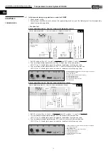
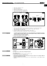
1� Constant supply air temperature contol
The external duct temperature sensor (TFK) is mounted in the supply air duct after the heater battery (see SS-953/
1
).
The electronic control unit WHSE prevents any temperature deviation between the actual value and the preset setpoint.
The cascade factor
CF must be set to 1
. The setpoint is adjusted on the control unit and keeps T
set
constant.
2� Constant room air temperature contol
For constant room air temperature contol, the external room temperature sensor (TFR) must be mounted vertically in a
suitable location in the room (see SS-953 /
2
); close window proximity and drafts must be avoided.
The setpoint is adjusted on the room temperature sensor (TFR), thus a constant room temperature can be achieved.
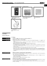
Technical data:
Temperature range: 0 – 30 °C Protection class: IP 20 Dimensions (w x h x d): 70 x 70 x 30 mm
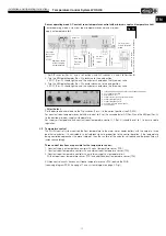
3� Constant room air temperature contol with minimum supply air temperature limit
The control unit WHSE works as a cascade controller with a minimum supply air temperature limit. The external
room temperature sensor (TFR) is located in the room and an additional duct temperature sensor (TFK) is mounted in
the air duct after the WHR heater battery (see SS-953 /
3
).
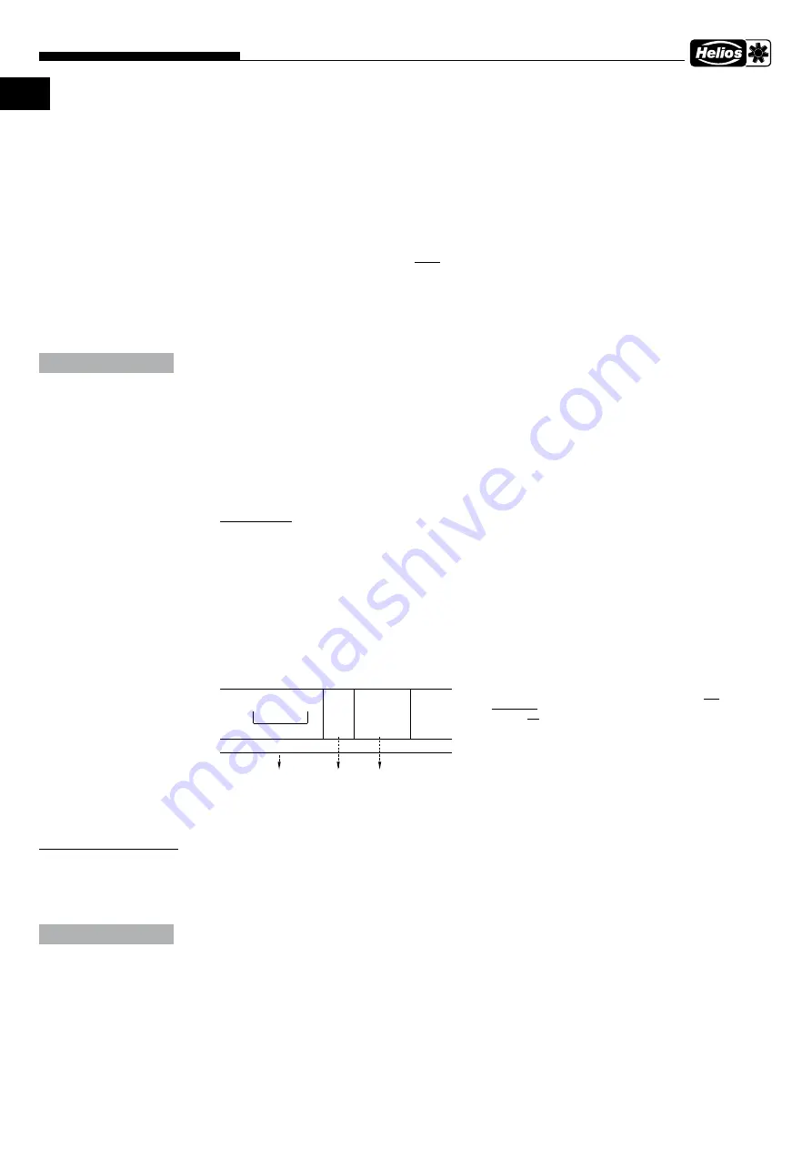
If the room temperature is higher or equal to the preset setpoint, the controller will keep the supply air temperature at
the preset minimum value. If the room temperature falls below the setpoint temperature, the controller increases the
supply air temperature above the preset minimum value. The value of the temperature increase is determined by the
cascade factor CF. A cascade factor of 5 means, for example, that the supply air temperature change is five times the
room temperature change.
Other functions:
Setpoint control
(e.g. for night and weekend reduction)
The setpoint can be adjusted between -15 K and +15 K by means of a 0–10 VDC signal at input 13 and 14. In this
respect, the existing setpoint input is overridden. A voltage of 5 V or an open terminal 13 will result in no adjustment.
4�1 Maintenance and servicing
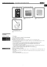
The safety instructions in chapter 1�3 must be observed!
It must be ensured that the assembly has been disconnected from the mains power before any work!
In principle, the assemblies are maintenance-free, user maintenance is not envisaged. However, any necessary main-
tenance work must be carried out by authorised, qualified personnel!
After maintenance and servicing work, the following must be checked:
• fittings, water connections and pipes are tightly fitted
4�2 Spare parts
Only Helios original spare parts must be used. All repairs must only be carried out by authorised, qualified personnel/
companies.
4�3 Decommissioning and disposal
Dispose of the components used according to the locally applicable regulations and laws.
ATTENTION
T
set
= 20 °C
3 °C
5 = 15
+ 15
= 30 °C
x
T
act.
= 17 °C
Difference
T
min
= 15 °C Supply air
temp.*
C
F
= 5
*
as the calculated supply air temperature depends on the flow
temperature and air flow, the calculated supply air tempera-
ture may not be achieved at high CF values.
Example:
CHAPTER 4
MAINTENANCE AND
SERVICING
ATTENTION

