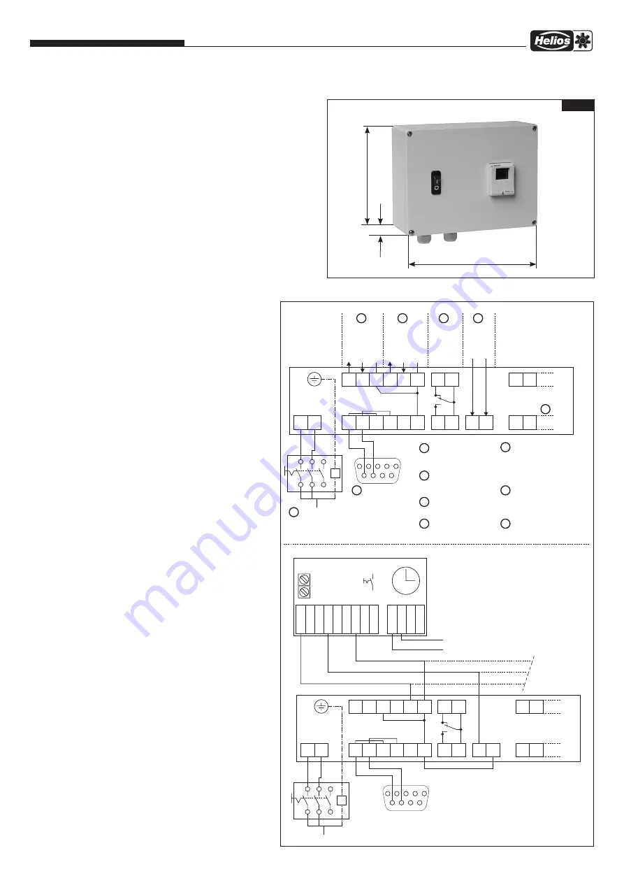
Electronic Timer Module ZLS-ZU 31
Installation and Operating Instructions
4.0 Dimensions (in mm)
150
200
75
Fig.1
Prinzip für ZLS-DVEC Anschluss
L N
18VE
soll
GND
U3
10V
RS
A
RS
B
RS
A
RS
B
E
soll
GND
U3
GND
U3
An
Ö G
G
S
EN
+
Motor Anschluss
1
2
3
4
5
6
7
8
9
230V~
Sensor
Sollwert
Relais
Alarm
Freigabe
RS 485
SUB-D 9, Buchse
+18VDC
+0-10VDC
-
+10VDC
+0-10VDC
-
10VDC
bis
230VAC
EN
-
WS
1
2
3
4
5
6
7
1
2
3
4
5
6
7
WS-
Wartungsschalter
RS 485
Schnittstelle
Sensor
Sollwerteingang
0-10VDC
Relais Ausgang
(bei Alarm G-S
geschlossen)
Eingang für
Startfreigabe
Anschluss
EC-Motor
1
2
3
4
5
6
Anschluss mit ZLS-ZU 31 Zeitschaltuhr
L N
18VE
soll
GND
U3
10V
RS
A
RS
B
RS
A
RS
B
E
soll
GND
U3
GND
U3
An
Ö G
G
S
EN
+
Motor Anschluss
1
2
3
4
5
6
7
8
9
230V~
RS 485
SUB-D 9, Buchse
EN
-
WS
1
2
3
4
5
6
E
soll, UIT
E
soll, IN
EN, IN
EN, UIT
GND
GND
+10V
L
N
L
N
230V~
max. 30 weitere
ZLS-DVEC
ZLS-ZU 31
Freigabe
Ein/Aus
R1-Drehzahl 2
R2-Drehzahl 1
1 2
N
L
92791 SS-753 18.02.04
br
sw
bl
In der Schnellübersicht /
Kurzanleitung zum Gerät,
finden sich weitere
Anschlussbeispiele.
Wiring diagram SS-753
Connection of timer ZLS-ZU 31
to roof fan ZLS-DVEC
Connection principle for ZLS-DVEC
Setpoint
Relay
alarm
Release
10VDC
up to
230VAC
Motor connection
maintenance switch
interface
Setpoint input
Relay output
(for alarm G-S
closed)
Input for
start release
Connection
EC motor
Connection to ZLS-ZU 31 timer
connector
Release
on/off
R1 speed 2
R2 speed 1
Further connection options can
be found in the quick overview /
quick guide for the unit
max. 30 additional
ZLS-DVEC
Motor connection
connector
2


