4x
16x
C
E
B
2
1
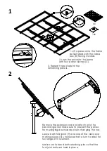
3. Repeat these steps for the
remaining panels.
1. Lift a panel onto the frame
as illustrated with the cable
box (B) facing inwards.
2. Lock the panel to the frame
with four panel clamps (C).
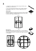
Remove the extension rod and attach only the
black angle rod. Make sure to prevent the panels
from swinging downwards when changing the rod.
Leave both fork joints (F) and one of the clevis eye
mating pieces (E) unscrewed half a turn to allow for
full range of movement.
Make sure to bend both retaining pins so that the
fork joint bolts are held in place.
F
C
Summary of Contents for HELIOMOTION PV-4
Page 1: ...QUICK ASSEMBLY GUIDE PV 4 HELIOMOTION HelioZenit Revision 1 2021...
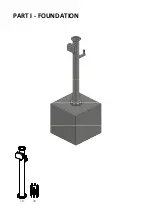
Page 2: ...1x 1x PART I FOUNDATION...
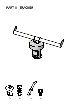
Page 6: ...1x 1x 6x 4x PART II TRACKER...
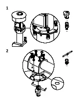
Page 7: ...6x 4x 1x 1x 1 2...
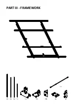
Page 8: ...2x 1x 1x 20x 2x 4x 1x 2x 4x 2x PART III FRAMEWORK...
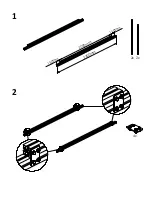
Page 9: ...2300mm 2000mm 150mm 150mm 2x 2x 4x 2 1...
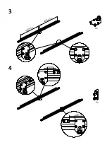
Page 10: ...2x 960mm 960mm 2x 45mm 45mm 4 3...
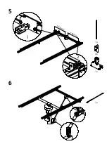
Page 11: ...592mm 592mm 1x 1x 4x 1 2 1x 5 6...
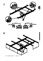
Page 12: ...16x 45mm 600mm 45mm 600mm 600mm 600mm 1324mm X X 4x 8 7 X Panel width 2 1324 2...
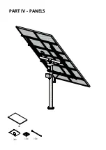
Page 13: ...4x 10x 10x 16x PART IV PANELS...


