background image

22

Technical Data

The  warranty  service  is  based  on  the  statutory 

regulations. Defects and damage caused by over

-

load or improper handling are excluded from the 

warranty service. Any return can only take place 

following prior consultation, in the original packag-

ing together with a detailed description of the error 

and a valid proof of purchase. 

Technical modifications, misprints and errors ex

-

cepted! We accept no liability for damage to the 

vehicle or device defects caused by the incorrect 

operation of the device. This product has been is

-

sued a CE marking. This means that the device is 

certified  for  use  in  vehicles  within  the  European 

Union (EU).

Warranty Disclaimer 

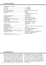
Power RMS ≤


1% THD+N

- @ 4 Ohms ..................................................................

1 x   500 Watts

- @ 2 Ohms ..................................................................

1 x   880 Watts

- @ 1 Ohm ....................................................................

1 x 1.500 Watts

Max. output power per channel*

 ................................... Up to 1,800 Watts RMS @ 1 Ohm

Amplifier technology

 .....................................................Class D

Inputs ............................................................................

 2 x RCA / Cinch


1 x Optical SPDIF (28 - 96 kHz)


1 x Remote In

Input sensitivity

 ............................................................. RCA / Cinch: 0.5 V - 8 V

Input impedance ........................................................... RCA / Cinch: 20 kOhms

Outputs .........................................................................

 1 x Speaker output

Signal converter for the digital input

 .............................

BurrBrown 32 Bit DA converter

Frequency range ..........................................................21 Hz - 40,000 Hz

Subsonic filter

 ...............................................................21 Hz / Butterworth 48 dB/Okt.

Signal-to-noise ratio (A-bewertet) ................................. Digital input:   110 dB 

Analog input:  110 dB

Distortion (THD) ............................................................< 0.01 %

Damping factor .............................................................> 450

Operating voltage

 .........................................................

10.5 - 17 Volts (max. 5 sec. down to 6 Volts)

Idle current....................................................................1500 mA

Fuse..............................................................................

4 x 30 A LP-Mini-fuse (APS) 

Power rating .................................................................DC 12 V 

 160 A max.

Ambient operating temperature range ..........................-40 °C to +70 °C

Additional features ........................................................ Input mode switch, SPDIF Direct In switch, 

Start-Stop capability

Dimensions (H x W x D)

 ...............................................

50 x 260 x 190 mm / 1.97 x 10.24 x 7.48”

* In typical applications as subwoofer amplifier

Summary of Contents for DE 29323089

Page 1: ...1 Kanal High Res Verst rker mit digitalem Signaleingang 1 channel High Res amplifier with digital signal input User Manual Bedienungsanleitung de en P ONE MK2...

Page 2: ......

Page 3: ...muss der Verst rker professionell befestigt werden Die ses geschieht ber Schrauben die in eine Mon tagefl che eingeschraubt werden die wiederum gen gend Halt bieten muss Bevor Sie die Schrauben im Mo...

Page 4: ...eite 5 Punkt 1 3 Clipping LED Seite 8 Punkt 2 4 Eingangsmodus Schalter Seite 5 Punkt 3 5 SPDIF DIRECT IN Schalter Seite 5 Punkt 4 6 Optischer Digitaleingang A B Seite 5 Punkt 2 7 Gain Regler Seite 6 P...

Page 5: ...elt Das bedeutet dass an s mtlichen Ausg n gen der P ONE MK2 der volle Pegel anliegt Dies kann im Extremfall die angeschlos senen Lautsprecher zerst ren Wir raten des halb dringend dazu nur lautst rke...

Page 6: ...Eingang dient zum Ein und Ausschalten der P ONE MK2 Dieser muss unbedingt mit dem Remote Ausgang der unmittelbar vorgeschalteten Komponen te welche das Eingangssignal f r die P ONE MK2 liefert verbund...

Page 7: ...hat einen To talverlust der Basswiedergabe zur Folge Der Pluspol ist bei den meisten Lautsprechern ge kennzeichnet Die Impedanz darf 1 Ohm nicht unterschrei tenn da sonst die Schutzschaltung des Ver...

Page 8: ...digung des Ger tes zu verhindern H here Werte k nnen zu gef hr lichen Folgesch den f hren Rot Protection Mode aktiv Dieser kann unter schiedliche Ursachen haben Der Verst rker ist mit verschiedenen e...

Page 9: ...rden parallel geschaltet Hinweis Die Parallelschaltung von zwei Schwingspulen f hrt zur Halbierung der Impedanz RMS Ausgangsleistung 1 THD N Zwei Subwoofer mit 1 x 4 Ohm entsprechen einer Gesamtimpeda...

Page 10: ...ner Gesamtimpedanz von 4 Ohm 500 Watt Ein Subwoofer mit 2 x 2 Ohm entspricht ebenso einer Gesamtimpedanz von 4 Ohm 500 Watt Zwei Subwoofer mit 1 x 1 Ohm entsprechen einer Gesamtimpedanz von 2 Ohm 880...

Page 11: ...st rker Eingang Input Mode Schalter SPDIF Direct In Schalter Interner Subsonic Filter P ONE MK2 Links Optical Input A B Mono A An On Aus Off P ONE MK2 Rechts Optical Input A B Mono B An On Aus Off WIC...

Page 12: ...mgebungstemperaturbereich f r den Betrieb 40 C bis 70 C Zus tzliche Features Eingangsmodus Schalter SPDIF Direct In Schalter Start Stopf higkeit Abmessungen H x B x T 50 x 260 x 190 mm In typischen An...

Page 13: ...ELIX P ONE MK2 amplifier The HELIX P ONE MK2 amplifier may only be in stalled in vehicles which have a 12 Volts negative terminal connected to the chassis ground Any other system could cause damage to...

Page 14: ...inputs Page 15 point 1 3 Clipping LED Page 18 point 2 4 Input mode switch Page 15 point 3 5 SPDIF DIRECT IN switch Page 15 point 4 6 Optical digital input A B Page 15 point 2 7 Gain control Page 16 po...

Page 15: ...age to your speakers We strongly rec ommend to only use volume controlled audio sources For example DSP devices with opti cal signal output like P SIX DSP ULITMATE BRAX DSP etc Note The HELIX P ONE MK...

Page 16: ...signal to the P ONE MK2 For ex ample the remote output of a preconnected P SIX DSP ULTIMATE We do not recommend controlling the remote input via the ignition switch to avoid pop noise during turn on...

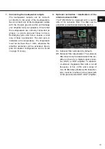
Page 17: ...amplifier protection will be activated Exam ples for speaker configurations can be found on page 19 et sqq 8 Optional Activation deactivation of the internal subsonic filter The P ONE MK2 is equipped...

Page 18: ...placed by identically rated fuses 4 x 30 Am pere to avoid damage of the amplifier Red A malfunction has occurred that may have different root causes The HELIX P ONE MK2 is equipped with protection cir...

Page 19: ...el connection of two voice coils will result in halving the impedance RMS output power 1 THD N Two subwoofers with 1 x 4 Ohms correspond to a total impedance of 2 Ohms 880 Watts One subwoofer with 2 x...

Page 20: ...1 x 2 Ohms correspond to a total impedance of 4 Ohms 500 Watts One Subwoofer with 2 x 2 Ohms also corresponds to a total impedance of 4 Ohms 500 Watts Two subwoofers with 1 x 1 Ohm correspond to a tot...

Page 21: ...Optical Input A B Mono A On Off P ONE MK2 Right Optical Input A B Mono B On Off IMPORTANT The crossover frequencies for the high and lowpass must be set in the preconnected DSP DSP amplifier We recom...

Page 22: ...80 Watts 1 Ohm 1 x 1 500 Watts Max output power per channel Up to 1 800 Watts RMS 1 Ohm Amplifier technology Class D Inputs 2 x RCA Cinch 1 x Optical SPDIF 28 96 kHz 1 x Remote In Input sensitivity RC...

Page 23: ...en...

Page 24: ...Audiotec Fischer GmbH H negr ben 26 57392 Schmallenberg Germany Tel 49 2972 9788 0 Fax 49 2972 9788 88 E mail helix audiotec fischer com Internet www audiotec fischer com...

Reviews: