


26
Installation
Note:
The setting of the potentiometers affects
both the lowlevel and the highlevel inputs!
Follow the subsequent steps to perfectly adapt
the signal processors input sensitivity to your
audio source by using the control (The adjust-
ment will be easier when you connect and ad-
just one input channel after the other):
1. Don‘t connect any amplifiers to the outputs
of the HELIX DSP ULTRA during this setup.
2. Turn on the signal processor.
3. Adjust the volume of your radio to approx.
90 % of the max. volume and playback a
1 kHz full scale test tone (0 dB) via CD drive.
4. If the
Clipping LED
already lights up, you
have to reduce the input sensitivity via the
respective control until the LED turns off.
5. Increase the input sensitivity by turning the
control clockwise until the LED lights up.
Now turn the control counterclockwise until
the
Clipping LED
turns off again.
6. Repeat this process for each channel you
are using.
Important: If the input sensitivity of a chan-
nel is set between 11 V and 32 V, it is man-
datory to remove the Load Jumper inside
the device immediately (see below, item 5).
Disregarding this may cause severe damage
to the processor.
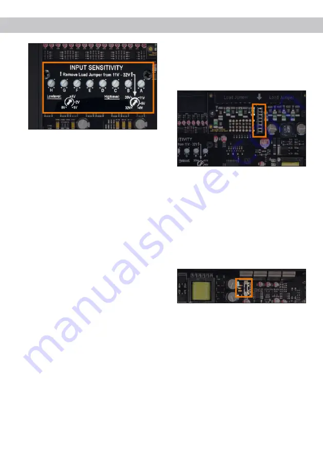
5. Adjustment of the highlevel input load
Attention: If the highlevel input is used as
signal input it is mandatory to adapt its load
to the input voltage in order to avoid dam-
age to the signal processor.
As soon as the input sensitivity of an individual
channel is set between 11 V and 32 V, the Load
Jumper inside the device has to be removed –
e.g. if an OEM amplifier is used as signal
source. To get access to the Load Jumper the
device has to be opened as described in item 4,
Adjustment of the input sensitivity
. To remove
the Load Jumper (see marking in the picture
below) simply pull it upwards.
6. Adjustment of the ground connection
The signal ground of the HELIX DSP ULTRA is
galvanically decoupled from the power ground.
In many cars this setup is the best way to avoid
alternator noise. Nevertheless, there are use
cases where it will be necessary to tie signal
and power ground together directly or to con-
nect them via a 200 ohms resistor softly. To get
access to the ground lift switch and change the
ground setting the device has to be opened as
described in item 4,
Adjustment of the input
sensitivity
.
- center position: input and output ground sep-
arated.
- left position: input and output ground tied to-
gether.
- right position: input and output ground con-
nected via 200 Ohms resistor.
7. Connection to power supply
Make sure to disconnect the battery before
installing the HELIX DSP ULTRA!
Solely use the included screw-type terminal to
connect the HELIX DSP ULTRA to a power sup-
ply. Make sure of correct polarity. The ground
wire must be connected to the vehicle chassis
at a non-insulated point. Inadequate grounding
causes audible interference and malfunctions.


