background image

Connection

1

.1

Digital Signal-Input

The 

HELIX DXP-6

has a Digital Signal-Input which has to be

connected to the pre-amplifier-output of the head-unit. 

2

.1

Analog Signal-Input 

The 

HELIX DXP-6

offers 4 RCA-connectors which generate 2

Stereo-Signals. Thus, the 

HELIX DXP-6 

can be connected to the

pre-amlifier-output of the head-unit by using Cinch-plugs. 

3

.1

Signal-Output, Channel 1-6 

The Signal-Outputs have RCA-connectors which are connected to

the input of the downstream amplifier.

4

.1

Power Connector: Ground Cable

The Ground Cable should be connected to a to a dismantled, unla-

quered ground point of the car chassis.

5

.1

Power Connector: + 12 Volt

The +12V-Cable has to be connected to a positive pole.  

6

.1

Power Connector: Remote-Input

The Remote-Input has to be connected to the remote output of

the head-unit. It is only active if the head-unit in ON. Thus, the

HELIX DXP-6

is switched on and off automatically togehter with the

head-unit.

7

.1

Power Connector: Remote-Output

The Remote-Output has to be connected to the Remote-Input of

the downstream amplifiers. If this is neglected, static noise can

occur when the amplifiers are switched on or off. 

Operation

8

.1

Control Unit

Via the Control Unit the Digital Crossover 

HELIX DXP-6

can be

operated in three different control modes:

- NORMAL MODE

- SETUP MODE

- TEST TONE MODE 

8.1

.1

Normal Mode

The Normal Mode starts after the 

HELIX DXP-6

has been swit-

ched on via the Remote-Input-Signal. The Input-Source (analog/

digital) can be chosen in the Normal Mode. Moreover, the Bass

Level for the Output-Channels 1-6 can be adjusted. 

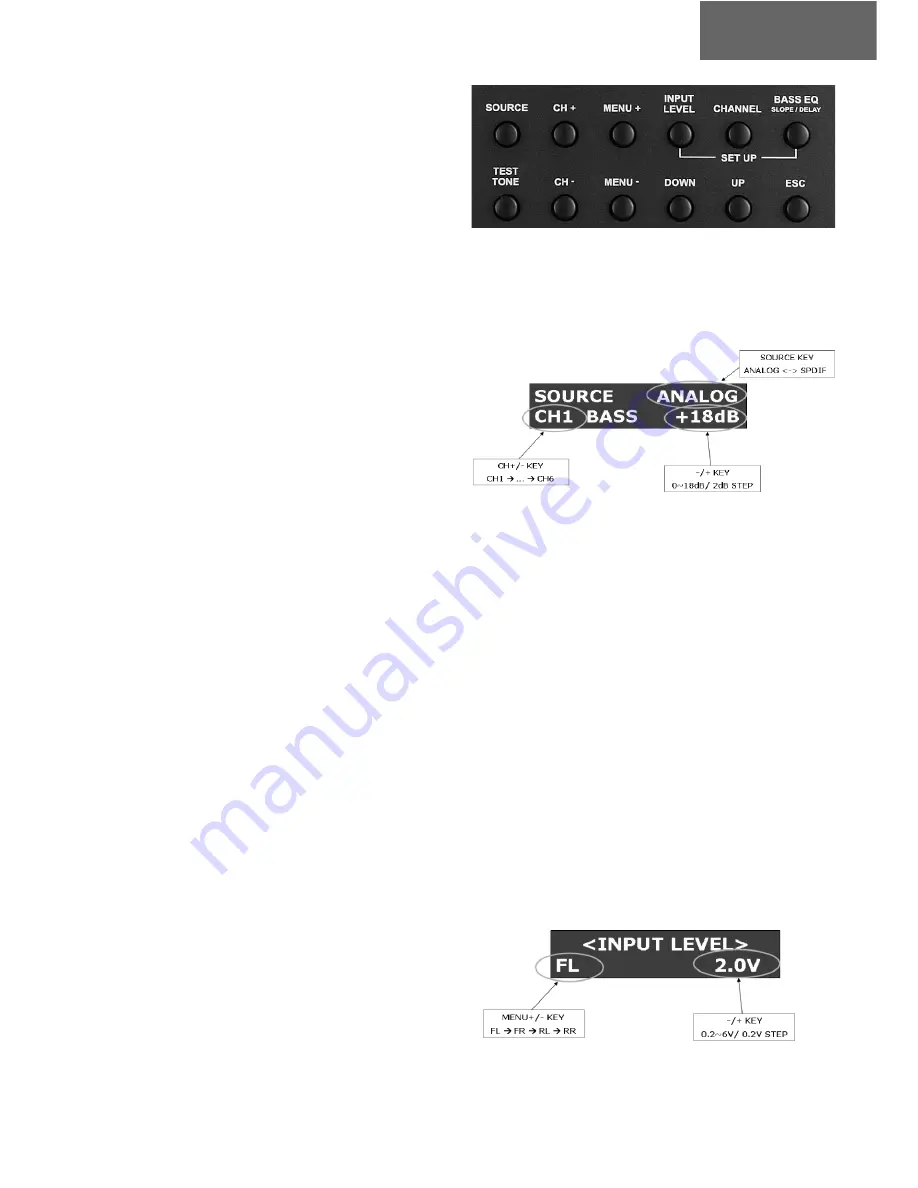
8.1.1  Selection of the Input-Source

Using the SOURCE-key, either the analog or the digital input

mode can be chosen.  

8.1.2  Adjustment of the Bass Level

Using the keys UP and DOWN the Bass Level can be adjusted in

2-dB-steps from 0 to 18 dB. The respective Output-Channel can

be chosen via the keys CH+ und CH

.

8.2

.1

Setup Mode

The following adjustments can carried out in the Setup-Mode:

- INPUT LEVEL SETUP (only analog)

- CHANNEL SETUP

- BASS EQ SETUP 

8.2.1  Input Level Setup

Using the key INPUT LEVEL the respective menu can be chosen.

Via the keys UP and DOWN the Input Level can be adjusted.

9

english

Summary of Contents for DXP-6 Competition

Page 1: ...B E D I E N U N G S A N L E I T U N G I N S T R U C T I O N M A N U A L deutsch english DXP 6 Competition 6 Kanal Digitale Frequenzweiche 6 Channel Digital Crossover ...

Page 2: ...rkulation oder in der Nähe von wärmeabstrahlenden Teilen oder elektroni schen Steuerungen des Fahrzeuges Im Sinne der Unfallsicherheit muß die Frequenzweiche professio nell befestigt werden Dieses geschieht über die beiliegenden Schrauben die in eine Montagefläche eingeschraubt werden die genügend Halt bieten muss Bevor Sie die Schrauben im Montagefeld befestigen vergewissern Sie sich daß keine el...

Page 3: ...l Ausgang Kanal 1 6 Power Connector Massekabel 1 2 3 4 AUSSTATTUNG UND BEDIENELEMENTE HELIX DXP 6 5 6 7 8 Power Connector 12 Volt Power Connector Remote Eingang Power Connector Remote Ausgang Bedieneinheit FUNKTIONALES BLOCK DIAGRAMM 3 2 3 4 5 6 7 8 deutsch ...

Page 4: ...st Störgeräusche beim Ein und Ausschalten der Endstufen entstehen können Bedienung 8 1Bedieneinheit Mit der Bedieneinheit kann die Frequenzweiche eingestellt wer den Der HELIX DXP 6 verfügt über drei verschiedenen Betriebsarten NORMAL MODE Normal Modus SETUP MODE Setupl Modus TEST TONE MODE Test Ton Modus 8 1 1 Normal Mode Normal Modus Der Normalmodus startet nachdem der HELIX DXP 6 über das Remot...

Page 5: ... inch Channel Routing FL FR RL RR FL and FR mix RL and RR mix Polarität Normal Invert 8 2 3 Bass EQ Setup Bass Equalizer Setup Durch Betätigung der Taste BASS EQ wird das entsprechende Menü aufgerufen Mit den Tasten MENU und MENU wird die einzustellende Funktion ausgewählt Die entsprechenden Einstellungen lassen sich über die Tasten UP und DOWN vorneh men Center Frequency 45 Hz 60 Hz Bandwith Narr...

Page 6: ... Risiko gehen zu Ihren Lasten d Die Kaufquittung muss beiliegen 5 Von der Garantie ausgenommen sind a Transportschäden sichtbar oder unsichtbar Reklama tionen für solche Schäden müssen umgehend bei der Transportfirma eingereicht werden b Kratzer in Metallteilen Frontabdeckungen usw Diese Defekte müssen innerhalb von 5 Tagen nach Kauf direkt bei Ihrem Händler reklamiert werden c Fehler die durch fe...

Page 7: ...icient retention and sta bility Before drilling the holes for the screws carefully examine the area around the installation position and make sure that there are no electrical cables or components hydraulic brake lines or any part of the petrol tank located behind the mounting surface otherwi se these could be damaged You should be aware of the fact that such components may also be concealed in th...

Page 8: ...Output Channel 1 6 Power Connector Ground 1 2 3 4 5 6 7 8 Power Connector 12 Volt Power Connector Remote Input Power Connector Remote Output Control Unit 8 english 1 EQUIPMENT AND CONTROL UNIT OF THE HELIX DXP 6 2 3 4 5 6 7 8 FUNCTIONAL BLOCK DIAGRAM ...

Page 9: ...ote Output has to be connected to the Remote Input of the downstream amplifiers If this is neglected static noise can occur when the amplifiers are switched on or off Operation 8 1Control Unit Via the Control Unit the Digital Crossover HELIX DXP 6 can be operated in three different control modes NORMAL MODE SETUP MODE TEST TONE MODE 8 1 1 Normal Mode The Normal Mode starts after the HELIX DXP 6 ha...

Page 10: ...z 30 Hz Bass EQ Level 0 dB 18 dB Channel Trim Level 6 dB 6dB Delay Time 0 14 ms 480 cm 189 inch Channel Routing FL FR RL RR FL and FR mix RL and RR mix Polarity Normal Invert 8 2 3 Bass EQ Setup Bass Equalizer Setup By using the key BASS EQ the respective menu can be chosen Select the desired function with the keys MENU and MENU The settings can be made via the keys UP and DOWN Center Frequency 45...

Page 11: ...receipt invoice as proof of purchase is enclosed 5 Excluded from the warranty are a Shipping damages either readily apparent or concea led claims for such damages must be immediately notified to the forwarding agent b Scratches in metal parts front panels or covers etc This must be notified to your dealer within 5 days of purchase c Defects caused by incorrect installation or connec tion by operat...

Page 12: ...Audiotec Fischer GmbH Huenegraeben 26 D 57392 Schmallenberg Tel 49 2972 97880 Fax 49 2972 978888 www audiotec fischer com helix audiotec fischer com ...

Reviews: