28
Important:
It is strictly forbidden to use the
High-
level Input
and lowlevel
Line Input
of an individual
channel at the same time as this may cause severe
damage to the lowlevel line outputs of your car ra-
dio. Nevertheless it is possible to use the
Highlevel
Input
of one channel and the lowlevel
Line Input
of
another channel simultaneously.
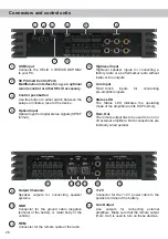
6
Line Input
6-channel pre-amplifier input to connect signal
sourc
es such as radios. Input sensitivity is
factory-set to 2.8 Volts.
It is possible to optimally adapt the input sensitivity
to the signal source using the DSP PC-Tool software
(DCM menu → Signal management) and by repo
-
sitioning jumpers inside the device (see page 30,
point 4; Adjustment of the input sensitivity).
7
Status LED
The
Status LED
indicates the operating mode of the
amplifier and of its memory.
Green:
Amplifier is ready for operation.
Orange:
Power Save Mode is active.
Red:
Protection Mode is active. This may have differ
-
ent root causes. The HELIX V TWELVE DSP MK2
is equipped with protection circuits against over-
and undervoltage as well as overheating. Please
check for connecting failures such as short-circuits
or other wrong connections.
If the amplifier is overheated the internal tempera
-
ture protection switches off the remote and signal
output until it reaches a safe temperature level
again.
Red
/
green
slow flashing:
No operating soft-
ware installed. Connect the amplifier to the DSP
PC-Tool software and confirm the automatic up
-
date of the operating system. You will find the
latest version of the DSP PC-Tool software at
www.audiotec-fischer.com.
Red
/
green
fast flashing:
The currently selected
sound setup memory is empty. A new setup has to
be loaded via the DSP PC-Tool software or switch
to a memory position with existing sound setup.
8
Rem. Out
We strongly recommend to use this output for turning
on / off additional amplifiers that are connected to
the
Line Output
of the HELIX V TWELVE DSP MK2.
This is essential to avoid any interfering signals.
This output is activated automatically as soon as
the booting process of the DSP is completed. Ad-
ditionally this output will be turned off during the
“Power Save Mode” or a software update process.
9
Output Channels
Speaker outputs to connect speaker systems. The
impedance per channel must not be lower than
2 Ohms.
Important:
We highly recommend to make the gen-
eral settings in the DSP PC-Tool software before the
first start-up. Especially if the V TWELVE DSP MK2
will be used to drive fully active speaker systems, a
wrong setup can destroy your tweeters right away.
10
GND
The ground cable should be connected to a common
ground reference point (this is located where the
negative terminal of the battery is grounded to the
metal body of the vehicle) or to a prepared metal lo-
cation on the vehicle chassis i.e. an area which has
been cleaned of all paint residues. Recommended
cross section: min. 16 mm² / AWG 6.
11
REM
The remote input has to be used to turn on / off the
V TWELVE DSP MK2 if the signal source which is
connected to the
Highlevel Input
is not activating
the “automatic turn-on” function or if the amplifier
shall only be activated / deactivated by a remote
signal applied to the remote input. The remote lead
should be connected to the remote output / auto-
matic antenna (aerial positive) output of the head
unit / car radio. This is only activated if the head
unit is switched on. Thus the amplifier is switched
on and off together with the head unit. This input
needn´t to be assigned if the
Highlevel Input
is
used. To deactivate the “automatic turn-on” function
Initial start-up and functions

