4
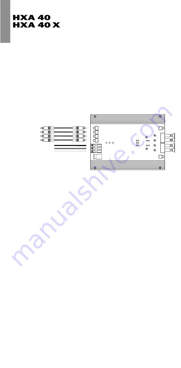
1
8
7
6
5
3
2
11 10 9
D
C
B
A
D
C
B
A
13
14
12
18
16
15
17
20
19
21
22
23
24
28
27
26
25
ENGLISH
Dear Customer,
congratulations for purchasing this high-quality
Helix
amplifier, made in Germany. This new Helix amplifiers
highlights best quality, excellent manufacturing and state-
of-the-art technology. They are the optimum completion of
Helix
Performance Line by Audiotec Fischer. To find out how
Helix
amplifiers work best for you, read this manual care-
fully and follow the instructions for installation.
We guarantee that this product has been checked for
proper functioning before shipping.
We wish you a lot of fun with your new
Helix
amplifier.
Yours,
Audiotec Fischer Team
Installation Instructions
Before you start installation, disconnect the car battery at
the minus pole. We would urge you to have the
installation work carried out by an authorized specialist as
verification of correct installation and connection is a pre-
requisite for warranty cover of the Helix amplifiers.
Install your amplifier at a dry location with sufficient air cir-
culation to ensure adequate cooling of the equipment. For
safety reasons, the amplifier must be secured in a profess-
sional manner. For this use the attached four fixing screws
and fix them into a mounting surface offering sufficient
stability.
Before drilling the holes for the screws, carefully examine
the area around the installation position and make sure
that there
Before drilling the holes for the screws, carefully examine
the area around the installation position and make sure
that there are no electrical cables or components, hydraulic
brake lines or any part of the tank located behind the
mounting surface – otherwise these could be damaged.
You should be aware of the fact that such components may
also be concealed in the double-skin trim panels/ mouldings.
Instruction for connecting the amplifier
The Helix HXA 40/ HXA 40X may only be installed in motor
vehicles which have a 12-volt minus pole connected to the
chassis ground. Any other system could cause damage to
the amplifier and the electrical system of the vehicle.
The plus cable from the battery for the complete system
should be provided with a main fuse at a distance of max.
30 cm from the battery. The value of the fuse is calculated
from the max. total current input of the car audio system.
Install the cabling in a manner which precludes any
danger of the leads being exposed to shear, crushing or
rupture forces. If there are sharp edges in the vicinity (e.g.
holes in the bodywork) all cables must be cushioned and
protected to prevent fraying.
Never lay the power supply cables adjacent to leads and
lines connecting other vehicle equipment (fan motors, fire
detection modules, gas lines etc.).
In order to ensure safe installation use only high quality
connectors and materials. Ask your dealer for
Brax and
Helix
accessories.
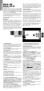
1 Connecting the remote wire
The remote wire is connected to the automatic antenna
(aerial positive) output of the head unit (radio). This is only
activated if the head unit is switched ON. Thus the amplifier
is switched on and off with the head unit.
2 Connecting the battery cable
Connect the +12 V cable to the positive terminal of the
battery. Recommended cross section: 10 mm
2
.
3 Connecting the ground cable
The ground cable should be connected to a central ground
reference point (this is located where the negative terminal
of the battery is grounded at the metal body of the vehi-
cle), or to a bright bare-metal location on the vehicle
chassis, i.e. an area which has been cleaned of all paint
residues.
4 Fuse
The input fuse provides protection against internal
equipment fault, i.e. the system must be additionally
protected by a further line fuse located near the battery
(max. distance from the battery: 30 cm/ 12 inch). The fuse
value of the amplifier is 30 Ampere.
5 - 8 Signal inputs
The HXA 40/ HXA 40X have RCA connectors for cinch cables
leading from the pre-amplifier outputs, the line outputs of
the head units or the outputs of a pre-amplifier/ equalizer,
e.g. HXE 100. These connectors are gold-plated in order to
ensure better signal transmission.
9 Green LED
When the green LED is on the amplifier is in operation.
10 Yellow LED
If the yellow LED is on there is a malfunction in the
amplifier or a short-circuit at the loudspeakers.
11 Red LED
The red LED turns on when the amplifier is overheated.
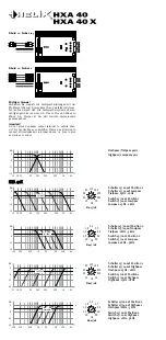
13 Selector switch for channels A and B
For switching the frequency crossover to highpass, lowpass
or full range.
14 Selector switch for channels C and D
For switching the frequency crossover to highpass, lowpass
or full range.
19 - 20 Switch for mono/ bridged and stereo
With this switch the channels A and B (19) and C and D (29)
can be bridged to mono. In this case the
total impedance
of the connected speakers
must be 4 ohm or higher.
In
stereo mode the connected total impedance per channel
can be
2 ohm
or higher.
In mono mode the total input sig-
nal of both channels cannot be higher than 8.5 V !
21 - 24 Level adjustment for input sensitivity
These controls can be used to match the input sensitivity
of the individual channels A to D to the output voltage of
the connected head unit. These controls are not volume
controls and are solely intended for the purpose of sensi-
tivity trimming. The adjustment range extends from
350 mV to 8.5 V.
controls and are solely intended for the purpose of sensi-
tivity trimming. The adjustment range extends from
350 mV to 8.5 V.
25 Speaker connection terminal for channels A and B
26 Speaker connection terminal for channels C and D
Integrated active crossover of HXA 40
The HXA 40 has an integrated active crossover of 90
Hz/ 12 dB Oct. The operating mode can be selected with
the switches 13 and 14.
Only for HXA 40X:
12 Selector for signal inputs
Position 1:
If there is only one
stereo signal
provided, use
switch 12 at position 1
only for the
inputs A and B
(only
this input RCA connectors can be used at position 1).
Position 2:
In this position all four inputs of the amplifier
can be used. On both positions the residual signal from
channel
C and D
is applied at the
RCA outputs 27 (C) and
28 (D).
Example:
HXA 40/ HXA 40X
channel C and D highpass
=RCA output 27
lowpass channel C
=RCA output 28
lowpass channel D
Position 3: Full active operating mode
The HXA 40X can be used in this operating mode for a full
active system. In this case the
inputs A and B
(only these
can be used in this mode), controlled by the
switches 13
and 15
with the use of
controller 17
, the frequencies for the
speaker outputs A and B
will be specified. The signal which
is not processed from both channels (remaining signal
from A and B) will be supplied to the channels C and D. At
this channels
C and D
the remaining signal will be specified
with the
switches 14 and 16
and
controller 18
. The signal that
remains of channel C and D is supplied to the
RCA connectors
27 and 28
where it can be used for connecting an addi-
tional amplifier.
Example: If A and B are used as highpass at 4 kHz, the
frequencies up to 4 kHz are provided to the channels C and D.
If the frequencies are used for highpass, i.g. 180 Hz, the chann-
nels C and D get a bandpass signal from 180 Hz to 4 kHz.
The frequencies up to 180 Hz are provided to the outputs
27 and 28 for connecting an additional
subwoofer amplifier.
15 - 16 Switch for selecting the frequencies range
With this switch the adjustment range of the potentiometers
17 and 18 can be selected from
15 Hz to 1 kHz at position 1
and from
1 kHz to 5 kHz at position 2.
17 - 18 Frequency controller
Frequency adjustment controller for the channels
A+B
(controller 17)
and
C+D (controller 18).
27 - 28 RCA outputs
The RCA outputs supply the residual signal for connecting
an additional amplifier. (look at point 12).


