background image

28

Installation

Connection of HELIX M FOUR DSP to the head 

unit / car radio:

Caution: 

Carrying out the following steps will re-

quire special tools and technical knowledge. In or-

der to avoid connection mistakes and / or damage, 

ask your dealer for assistance if you have any ques-

tions and follow all instructions in this manual (see 

page 23). It is recommended that this unit will be 

installed by an authorized HELIX dealer.

1.   Connecting the pre-amplifier inputs

  Use the correct cable (RCA / cinch cable) to 

connect  these  inputs  to  the  pre-amplifier  / 

lowlev el / cinch outputs of your head unit / car 

radio. Each input can be assigned to any output 

using the DSP PC-Tool software. The automat-

ic turn-on circuit does not work when using the 

pre-amplifier inputs. In this case the remote in

-

put has to be connected to activate the  HELIX 

M FOUR DSP. 

2.   Connecting the highlevel speaker inputs


The highlevel loudspeaker inputs can be con-

nected directly to the loudspeaker outputs of an 

OEM or aftermarket radio using appropriate ca-

bles (loudspeaker cables with 1 mm² / AWG 18 

max.). 

We recommend the following channel assign-

ment if a common car radio will be connected to 

the signal processor:

Channel A = Front left

Channel B = Front right

Channel C = Rear left

Channel D = Rear right

Actually it is not mandatory to use all high level 

speaker inputs. If only two channels will be con-

nected we recommend to use the channels A 

and B. Make sure that the polarity is correct. If 

one or more connections have reversed polarity 

it may affect the performance of the amplifier. 

If this input is used the remote input does not 

need to be connected as the amplifier will au

-

tomatically turn on once a loudspeaker signal 

is received.

3.  Connecting a digital signal source


If you have a signal source with an optical digi-

tal  output  you  can  connect  it  to  the  amplifier 

using the appropriate input. In standard con-

figuration the manual activation via an optional 

remote control is configured. 

Alternatively you can activate the automatic 

turn-on feature in the DCM menu of the DSP 

PC-Tool software. The feature activates the 

digital input as soon as a digital audio signal is 

detected. The automatic turn-on circuit does not 

work when a digital input is used. Therefore it is 

Fig. 1: 

Line Output connection cable

Summary of Contents for M FOUR DSP

Page 1: ...M FOUR DSP 4 Kanal Verstärker mit integriertem DSP 4 channel amplifier with integrated DSP deutsch english ...

Page 2: ...ss der Verstärker professionell befestigt werden Dieses geschieht über Schrauben die in eine Montagefläche ein geschraubt werden die wiederum genügend Halt bieten muss Bevor Sie die Schrauben im Montagefeld befesti gen vergewissern Sie sich dass keine elektrischen Kabel und Komponenten hydraulische Bremslei tungen der Benzintank etc dahinter verborgen sind Diese könnten sonst beschädigt werden Ach...

Page 3: ...ups oder zum Resetten des Gerätes 2 Rem Out Der Remote Ausgang dient zum Einschalten weiterer Verstärker 3 Highlevel Input Hochpegel Lautsprechereingang zum An schluss von Werksradios oder Radios ohne Vorverstärkerausgänge 4 Line Input Cinch Eingänge zum Anschluss eines Vorverstärkersignals 5 USB Eingang Dient zum Anschluss an den Computer 6 Status LED Die Status LED zeigt den Betriebszustand an 7...

Page 4: ...ngang Mit Hilfe dieses Eingangs kann der Verstärker direkt an die Lautsprecherausgänge eines Werks Nachrüstra dios oder eines Werksverstärkers angeschlossen werden sofern dieses dieser nicht über Vorver stärkerausgänge verfügt Die Eingangsempfind lichkeit ist für alle Kanäle ab Werk auf 20 Volt ein gestellt Mit Hilfe Der DSP PC Tool Software kann die Eingangsempfindlichkeit der Kanäle an die Ausga...

Page 5: ...dienung mit deren Hilfe diverse Funk tionen des Verstärkers gesteuert werden können Die Funktionalität muss je nach Typ der Fernbedie nung zuerst im Device Configuration Menu DCM der DSP PC Tool Software oder an der Fernbedie nung selbst konfiguriert werden 8 Optical Input Optischer Eingang im SPDIF Format für den An schluss an Signalquellen mit digitalem Ausgang Die Sampling Rate dieses Eingangs ...

Page 6: ...Verstärkers an Grün Verstärker eingeschaltet und betriebsbereit Rot Es besteht eine Fehlfunktion des Verstärkers Der Verstärker ist mit einer Schutzschaltung gegen Über und Unterspannung ausgestat tet Prüfen Sie in diesem Fall alle Anschlüsse auf Fehler wie z B Kurzschlüsse fehlerhafte Verbindungen oder Falscheinstellungen Sollte sich der Verstärker nach Beseitigung der Fehlerquelle nicht wieder e...

Page 7: ... Querschnitt verbunden werden Sollten Sie ein normales Werksradio anschlie ßen empfehlen wir folgende Kanalbelegung Kanal A Vorne links Kanal B Vorne rechts Kanal C Hinten links Kanal D Hinten rechts Dabei müssen nicht zwingend alle Eingänge belegt werden Werden nur zwei Kanäle belegt empfehlen wir die Kanäle A und B zu verwen den Achten Sie bitte auf eine korrekte Polung Wenn Sie einen oder mehre...

Page 8: ...Eingang des Verstär kers über das Zündungsplus des Fahrzeugs zu steuern um Störgeräusche beim Ein und Aus schalten zu vermeiden Bei Verwendung des Hochpegel Lautsprechereingangs Highlevel Input muss der Remote Eingang nicht belegt werden sofern das angeschlossene Radio über BTL Ausgangsstufen verfügt 6 Konfiguration des Remote Eingangs Die Einschaltung der M FOUR DSP erfolgt au tomatisch bei Anste...

Page 9: ...lus und Minus zu Minus Vertauschen von Plus und Minus hat einen Totalverlust der Basswiedergabe zur Folge Der Pluspol ist bei den meisten Lautsprechern gekennzeichnet Die Impedanz pro Kanal darf 2 Ohm im Brücken betrieb 4 Ohm nicht unterschreiten da sonst die Schutzschaltung des Verstärkers aktiviert wird 10 Anschluss des Remote Ausgangs Dieser Ausgang Rem Out dient dazu einen am Line Output anges...

Page 10: ...woofer 2 Subwoofer Konfigurationslayout mit zusätzlicher M FOUR und M ONE aktives 3 Wege Frontsystem passives Rearsystem und Subwoofer Front L Full Front R Full Rear L Full Rear R Full Subwoofer Vorne Tieftöner Vorne Hochtöner Mitteltöner Speaker Output Line Output Hinten Koax oder Passivsystem Front L Full Front R Full Rear L Full Rear R Full Amp Out A Amp Out C Line Out E Amp Out B Amp Out D Lin...

Page 11: ...stem passives Rearsystem und Subwoofer Front L Full Front R Full Rear L Full Rear R Full Subwoofer C D gebrückt Hinten Koax oder Passivsystem Vorne Hochtöner Mitteltöner Speaker Output Line Output Für weitere Anwendungsfälle kontaktieren Sie bitte Ihren HELIX Fachhändler ...

Page 12: ...chnitt lesen Sie die wichtigsten Schritte zum Anschluss und der ersten Inbetrieb nahme 1 Laden Sie die DSP PC Tool Software unter www audiotec fischer com herunter und in stallieren diese auf ihrem Computer 2 Schließen Sie danach die M FOUR DSP mit dem beiliegenden USB Kabel an den Compu ter an Wenn Sie längere Distanzen zu über brücken haben verwenden Sie bitte eine aktive USB Verlängerung mit in...

Page 13: ...tert den bisherigen Umfang des Gerätes um eine neue Ebene an prozessierten Kanälen welche sich zwischen den Ein und Ausgängen befindet Insgesamt stehen acht zusätzliche prozessierte virtuelle Kanäle und zehn prozessierte Ausgangskanäle zur Verfügung Diese virtuelle Kanalebene bietet diverse Vorteile gerade in komplexen Systemkonfigurationen Die Hauptvorteile dieses Konzeptes sind folgende Ausgangs...

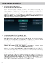
Page 14: ...r das Augmented Bass Processing aktiviert Diese sind nicht mehr fest mit den Ausgängen verknüpft sondern an bestimmte virtuelle Kanäle gebunden Front Processing virtuelle Kanäle Front L Full A und Front R Full B Center Processing virtueller Kanal Center Full E Augmented Bass Processing virtuelle Kanäle Subwoofer 1 I und Subwoofer 2 J An diese ist auch die Subwoofer Lautstärkeregelung gebunden Dadu...

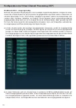
Page 15: ...d h die Eingangssignale auf der linken Sei te werden per Drag Drop auf die jeweilige Summierungsmatrix gelegt Der Unterschied zum normalen Modus ist dass die Namen und Signaleigenschaften der virtuellen Kanäle an dieser Stelle festgelegt sind Front L Full Front R Full Rear L Full Rear R Full Front Center Full etc a Zunächst müssen alle Eingangssignale auf die entsprechenden festgelegten Signaltype...

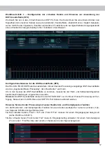
Page 16: ...e virtuellen Kanäle den jeweiligen Ausgangskanälen zuzuweisen werden im Ausgangsrouting Virtual to Output Routing die jeweiligen virtuellen Signale per Drag Drop auf die Ausgangskanäle gezogen An dieser Stelle müssen die Signale in der Regel nicht mehr summiert werden so dass je dem Ausgangs signal nur ein virtuelles Signal zugeordnet wird beispielsweise wird dem vorderen linken Hochtöner das Sign...

Page 17: ... Processing den RealCenter und mehr Um in den Genuss der DSP Soundeffekte zu kommen müssen bei der Hard und Softwarekonfiguration bestimmte Einstellungen vorgenommen werden Hinweis Die DSP Soundeffekte stehen bei der M FOUR DSP nur im Virtual Channel Processing zur Ver fügung Dieses kann im DCM Menü der DSP PC Tool Software aktiviert werden Hinweise für das Center Processing mit seiner RealCenter ...

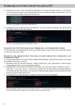
Page 18: ...s Augmented Bass Processing müssen bestimmte Einstellungen vorgenommen werden um dessen Soundeffekte anwenden zu können 1 Mindestens einer der virtuellen Subwoofer Kanäle Subwoofer 1 oder Subwoofer 2 muss mit einem Eingangssignal belegt sein siehe Workflow Schritt 1 2 Wechseln Sie in die Virtual to Output Routing Matrix und routen den Kanal die Kanäle Virtual I Subwoofer 1 und oder Virtual J Subwo...

Page 19: ...ngskanälen sein Im nachfolgenden Beispiel sind es die Vorverstärker Ausgänge Line Outputs I und J Anschließend wird die Subwoofer Regelung auch im Main Menü hinter der Kanalbezeichnung als SubRC angezeigt Hinweis Bitte beachten Sie dass den beiden virtuellen Subwoofer Signalen Subwoofer1 und oder Subwoofer2 zuvor in den anderen Routing Matrizen ein Eingangssignal zugewiesen werden muss Bei nicht a...

Page 20: ...erplätze um schalten Diese zwei Speicherplätze können in der URC Setup Switch Configuration festgelegt wer den Werkseitig sind die Speicherbereiche eins und zwei ausgewählt Um zwischen allen internen Spei cherplätzen umschalten zu können wird die optional erhältliche Display Fernbedienung DIRECTOR oder die HELIX WIFI CONTROL empfohlen Remote Output Configuration An dieser Stelle kann festgelegt we...

Page 21: ...funk tionen ausgestattet sodass bei Anschluss eines zusätzlichen Verstärkers Fehlermeldungen oder gar Fehlfunktionen auftreten können Der neue an den Diagnosemodus des Steuergeräts anpassbare ADEP 3 Schaltkreis Advanced Diagnostics Error Protection Generation 3 verhindert diese Probleme ohne die Lautsprecherausgänge des Radios bei hohen Pegeln unnötig zu belasten siehe Seite 20 ADEP 3 Configuratio...

Page 22: ...put Dämpfungsfaktor 100 Betriebsspannung 10 5 16 Volt max 5 Sek bis hinab zu 6 Volt Leerlaufstromaufnahme 1500 mA Max Remote Ausgangsstrom 500 mA Sicherung 2 x 30 A LP Mini Stecksicherung Zusätzliche Features ADEP 3 Schaltkreis Auto Remote Schalter 32 Bit CoProcessor Control Input Abmessungen H x B x T 50 x 230 x 154 mm In typischen Mehrkanal Anwendungen 2 3 Wege System Rear Subwoofer Technische D...

Page 23: ... behind the proposed instal lation location to insure that there are no electrical cables or components hydraulic brake lines or any part of the fuel tank located behind the mounting surface Failure to do so may result in unpredictable damage to these components and possible costly repairs to the vehicle General instruction for connecting the HELIX M FOUR DSP amplifier The HELIX M FOUR DSP amplifi...

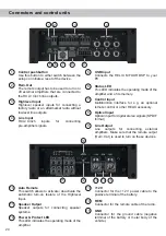
Page 24: ... the device 2 Rem Out The remote output has to be used to turn on off external amplifiers that are connected to the RCA Cinch line outputs 3 Highlevel Input Highlevel speaker inputs for connecting a factory radio or an aftermarket radio without lowlevel line outputs 4 Line Input RCA Cinch inputs for connecting pre amplifier signals 5 USB Input Connects the HELIX M FOUR DSP to your PC 6 Status LED ...

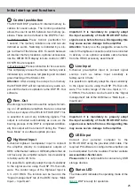
Page 25: ...utputs Input sensitivity is factory set to 20 Volts It is possible to optimally adapt the input sensitivity to the signal source using the DSP PC Tool soft ware The control range of the Highlevel Input is 5 V 20 V RMS The function can be found in the Signal management tab of the DCM menu Main Input Input Gain Important It is mandatory to properly adapt the input sensitivity of the M FOUR DSP to th...

Page 26: ...as soon as a music signal is detected to the Optical Input Note This amplifier can only handle stereo input signals and no Dolby coded digital audio stream Note In standard configuration the manual activa tion via an optional remote control is configured 9 Line Output Processed 6 channel pre amplifier output with a maximum output voltage of 6 Volts RMS for con necting additional power amplifiers P...

Page 27: ...emote input has to be used to turn on off the M FOUR DSP if the signal source which is con nected to the Highlevel Input is not activating the automatic turn on function or if the amplifier shall only be activated deactivated by a remote signal applied to the remote input The remote lead should be connected to the remote output automatic an tenna aerial positive output of the head unit car radio T...

Page 28: ...bles with 1 mm AWG 18 max We recommend the following channel assign ment if a common car radio will be connected to the signal processor Channel A Front left Channel B Front right Channel C Rear left Channel D Rear right Actually it is not mandatory to use all high level speaker inputs If only two channels will be con nected we recommend to use the channels A and B Make sure that the polarity is c...

Page 29: ... the Optical Input is solely are used as signal input s We do not recommend controlling the remote input via the ignition switch to avoid pop noise during turn on off If the Highlevel Input is used this input does not need to be connected as long as the car radio has BTL output stages 6 Configuration of the remote input The M FOUR DSP will be turned on automati cally if the Highlevel Input is used...

Page 30: ...t speakers The impedance of each channel must not be less than 2 Ohms 4 Ohms in bridged mode otherwise the ampli fier protection will be activated 10 Connecting the remote output This output Rem Out is used to supply remote signals to the external amplifier s Always use this remote output signal to turn on the ampli fiers in order to avoid on off switching noises Installation Examples for adjustin...

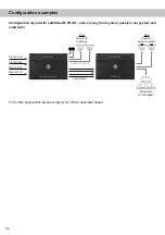
Page 31: ... To speakers Virtual channels Front L Full Front R Full Rear L Full Rear R Full Front L High tweeter FL Front L Mid midrange FL Front R High tweeter FR Front R Mid midrange FR Front L Low mid woofer FL Front R Low mid woofer FR Rear L Full fullrange RL Rear R Full fullrange RR Subwoofer 1 subwoofer Subwoofer 2 subwoofer Amp Out A Amp Out C Line Out E Amp Out B Amp Out D Line Out F Line Out G Line ...

Page 32: ...e 2 way front system passive rear system and subwoofer Front L Full Front R Full Rear L Full Rear R Full Subwoofer C D bridged Rear Coaxial or passive system Front Tweeter midrange Speaker Output Line Output For further applications please contact your HELIX specialist dealer ...

Page 33: ...C Tool software available on our website www audiotec fischer com and install it on your computer 2 Connect the amplifier to your computer us ing the USB cable that is included in delivery If you have to bridge longer distances please use an active USB extension cable with in tegrated repeater or the optionally available WIFI CONTROL interface 3 First turn on the amplifier and then start the softw...

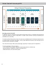
Page 34: ...pe of the device by an additional layer of processed channels which is located between the inputs and outputs A total of eight additional processed virtual channels and ten processed output channels are available This virtual channel layer offers several advantages especially in complex system configurations The main advantages of this concept are Cross channel group equalizers that affect several...

Page 35: ... RealCenter management or Augmented Bass Processing are also available These are no longer linked to the outputs but tied to specific virtual channels Front Processing virtual channels Front L Full A and Front R Full B Center Processing virtual channel Center Full E Augmented Bass Processing virtual channels Subwoofer 1 I and Subwoofer 2 J The subwoofer volume is also tied to these channels This m...

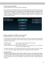
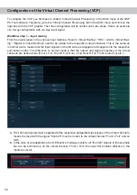
Page 36: ...me as in normal mode means that the input signals on the left side are dragged and dropped onto the respective summation matrix The difference to normal mode is that the names and signal properties of the virtual channels are defined here Front L Full Front R Full Rear L Full Rear R Full Front Center Full etc a First all input signals must be applied to the respective designated signal types of th...

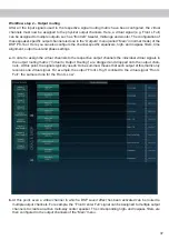
Page 37: ... assign the virtual channels to the respective output channels the individual virtual signals in the output routing matrix Virtual to Output Routing are dragged and dropped onto the output chan nels At this point the signals typically needn t to be summed means that each output of this matrix only receives one virtual signal For example the output Front L High is linked to the virtual signal Front...

Page 38: ...al Channel Processing is enabled In order to enjoy the DSP sound effects certain settings must be made in the hardware and software configuration Note The DSP sound effects are only available in the M FOUR DSP when Virtual Channel Processing is enabled VCP can be activated in the DCM menu of the DSP PC Tool software Notes for center processing with its features RealCenter and ClarityXpander To be ...

Page 39: ...ss Processing certain settings have to be made in order to use it 1 An input signal has to be assigned to at least one of the virtual subwoofer channels Subwoofer 1 or Subwoofer 2 see workflow step 1 2 Change to the Virtual to Output Routing matrix and route the channel s Virtual I Subwoofer 1 and or Virtual J Subwoofer 2 to the desired output channel or channels as described in workflow step 2 to...

Page 40: ... In the following example these are the pre amplifier outputs Line Outputs I and J If the VCP is not activated the subwoofer remote control of the M FOUR DSP is permanently assigned to the output channels I and J of the Line Outputs In this case it does not matter which output is named Subwoofer in the IO routing matrix In the main menu you can also see to which outputs the SubRC subwoofer remote ...

Page 41: ...ten memory locations These two memory lo cations can be determined in the URC Setup Switch Configuration The memory locations one and two are preassigned ex works To switch between all internal memory locations the optionally available DIRECTOR display remote control or the HELIX WIFI CONTROL is recommended Remote Output Configuration This function controls if the remote output which switches on a...

Page 42: ...tion quite often appear if an amplifier will be hooked up but not with the M FOUR DSP The new ADEP 3 circuit Advanced Diagnostics Error Protection 3rd Generation which can be adapted to the diagnostic mode of the radio avoids all these problems without loading the speaker out puts of the OE radio during high volumes unneces sarily see page 41 item ADEP 3 Configuration Start Stop capability The swi...

Page 43: ... dB Speaker Line Output A weighted Distortion THD 0 03 0 005 Speaker Line Output Damping factor 100 Operating voltage 10 5 16 Volt max 5 sec down to 6 Volts Idle current 1500 mA Max remote output voltage 500 mA Fuse 2 x 30 A LP Mini Fuse APS Additional features ADEP 3 circuit Auto Remote switch 32 Bit CoProcessor Control Input Dimensions H x W x D 50 x 230 x 154 mm 2 00 x 9 06 x 6 06 In typical mu...

Page 44: ...Audiotec Fischer GmbH Hünegräben 26 57392 Schmallenberg Germany Tel 49 2972 9788 0 Fax 49 2972 9788 88 E mail helix audiotec fischer com Internet www audiotec fischer com ...

Reviews: