26
However, it is possible to optimally adapt the input
sensitivity to the signal source using control 9 (
Gain
)
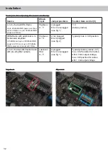
and by repositioning jumpers inside the device (see
page 28, item 4; Signal configuration).
Important: If the input sensitivity of a channel
is set between 11 V and 32 V, it is mandatory to
remove the Load Jumper inside the device be-
fore first use (see page 28, item 4; Signal con
-
figuration). Disregarding this may cause severe
damage to the amplifier.
Attention:
Solely use the pluggable screw-terminal
for the highlevel connector which is included in de-
livery or an optional available cable harness from
the HELIX accessory assortment!
Important:
It is strictly forbidden to use the
High-
level Input
and lowlevel
Line Input
of an individual
channel at the same time as this may cause severe
damage to the lowlevel line outputs of your car ra-
dio. Nevertheless it is possible to use the
Highlevel
Input
of one channel and the lowlevel
Line Input
of
another channel simultaneously.
7
Line Input
6-channel pre-amplifier input to connect signal
sourc
es such as radios. Input sensitivity is
factory-set to approx. 3 Volts.
However, it is possible to optimally adapt the input
sensitivity to the signal source using control 9 (
Gain
)
and by repositioning jumpers inside the device (see
page 28, item 4; Signal configuration).
8
Clipping LED
This LED lights up red if one of the six
Line Inputs
or eight
Highlevel Inputs
is overdriven. The LED has
no function if the device is fed with digital input sig-
nals. If this LED lights up reduce the input sensitivity
by using the control 9 (
Gain
) until the LED goes out.
9
Gain
This control is used to adapt the input sensitivity of
the low- and highlevel inputs to the output voltage
of the connected signal source. This is not a volume
control, it´s only for adjusting the amplifier gain. The
control range of the RCA /
Line Input
is factory-set
to 1 - 4 Volts and 4 - 16 Volts for the
Highlevel Input
.
The input sensitivity range can be changed by repo-
sitioning jumpers inside the device.
Alternatively, the input sensitivity can be set using
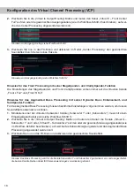
the DSP PC-Tool software. Therefore, the function
has to be activated and configured in the “Signal
management” tab of the DCM menu (see the fol
-
lowing picture).
Important: If the input sensitivity of a channel
is set between 11 V and 32 V, it is mandatory to
remove the Load Jumper inside the device be-
fore first use (see page 28, item 4; Signal con
-
figuration). Disregarding this may cause severe
damage to the amplifier.
Attention:
It is mandatory to properly adapt the
input sensitivity of the V EIGHT DSP MK2 to the
signal source in order to avoid damage to the am-
plifier.
10
Output Channels
Speaker outputs to connect speaker systems. The
impedance per channel must not be lower than
2 Ohms.
Important:
We highly recommend to make the gen-
eral settings in the DSP PC-Tool software before the
Initial start-up and functions

