CCR961 MANUAL-GB
16
Version B2:01-07-2015
Press the E key to get into the adjusting mode. The key is moreover used for acknowledging.
The 0 key is used to resetting any alarms. The key switch must be in the OFF position.
The most frequent adjustments are described in the Step-by-Step instruction.
3.4
The menu’s
There are more menu areas:
Normal menu (no access code needed) with the menu’s N1 – N12
User menu (user code) with the menu’s U1 – U 21
Factory menu (factory code) with the menu’s F1 – F19
Normal menu is only for display of data, while User and Factory menu are for setting and
adjustment of the CCR.
Below is given information about what can be read and done by means of the Normal menu, while
information about settings and possibilities in User and factory menus are given in section 5.2.
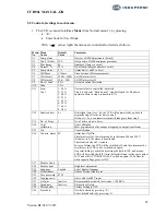
Normal menu:
Menu
no.
Menu information
Eventual special function
N1
Series circuit name
Actual output current
Actual selected intensity
step
Remote – Off – local
operation selected
Press >
←
<:
Lower text line shows: 10/(500-XXX), where
XXX is the actual trigger firing position (called “pyk).
The CCR always returns to this menu (after 2 min.).
Press >
↓
<:
Lower text line shows current mode, ISO mode and RS485
address
Press > E <:
Brings you directly to menu N7
N2
Actual output current
Actual output voltage
Actual input voltage
Actual output power
Press > E <:
When the CCR is set to “Learn” for lamp supervision (see 5.3.11)
it will automatically note and store the Z-value for each step (Z =
Uout / Iout)
N3 Lamp
Alarm
No. of faulty lamps
Press > E <:
N4 Circuit
Isolation
Last found value (can be 3
hours old)
Measuring active or off
Press >
↑
< :
Activates a new isolation measurement (also with CCR in Remote
Control).
N5 Hour
count
Total in 100% step
Total for all steps
System Temperature in °C
N6 CCR961
SW
version
Time
Date
RS485 address (node)
N7 Adjustment?
Enter Code
If you want to go to user or factory menu, enter the code and
press > E <


