CCR961 MANUAL-GB
30
Version B2:01-07-2015
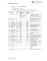
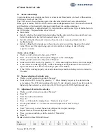
X
X ASCII: Latin Capital Letter X
Y
Y ASCII: Latin Capital Letter Y
Z
Z ASCII: Latin Capital Letter Z
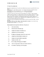
`
` ASCII: spacing grave
a
a ASCII: Latin Small Letter A
b
b ASCII: Latin Small Letter B
c
c ASCII: Latin Small Letter C
d
d ASCII: Latin Small Letter D
e
e ASCII: Latin Small Letter E
f
f ASCII: Latin Small Letter F
g
g ASCII: Latin Small Letter G
h
h ASCII: Latin Small Letter H
i
i ASCII: Latin Small Letter I
j
j ASCII: Latin Small Letter J
k
k ASCII: Latin Small Letter K
l
l ASCII: Latin Small Letter L
m
m ASCII: Latin Small Letter M
n
n ASCII: Latin Small Letter N
o
o ASCII: Latin Small Letter O
p
p ASCII: Latin Small Letter P
q
q ASCII: Latin Small Letter Q
r
r ASCII: Latin Small Letter R
s
s ASCII: Latin Small Letter S
t
t ASCII: Latin Small Letter T
u
u ASCII: Latin Small Letter U
v
v ASCII: Latin Small Letter V
w
w ASCII: Latin Small Letter W
x
x ASCII: Latin Small Letter X
y
y ASCII: Latin Small Letter Y
z
z ASCII: Latin Small Letter Z
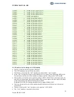
3.11
Procedure for the change of a CCR module
The Key switch is turned to position ”Manual”
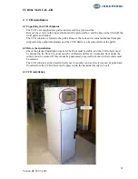
The CCR module is removed from the cubicle
The Memory-stick from the ”old” module is mounted in the ”new” module
In the ”new” module the remote control address is set by means of the belonging DIP-switch.
See instruction on the side of the module or simply copy the setting on the ”old” module.
The module is set for the correct operating voltage (230V / 400V). This is done by means of a
lead in the terminal block above the automatic fuses in the module. The lead must be mounted
in the terminal block marked 230V alternatively 400V.
If adjusted for 230V, the module should be clearly marked ”OBS: 230V”
The Log-schema on the side of the module should be filled-in with the name of the actual
serial circuit.
The Key switch on the ”new” module is set in position ”AUS” (OFF)
The ”new” module is mounted in the cubicle


