CCR961 MANUAL-GB
31
Version B2:01-07-2015
See, that the display seems to be working normally (no flashing)
The CCR module is switched-on in step 1, while observing the current in display. If the
module seems to be working, the other steps are tested.
In step 1, press the push button
2 times to get to the menu for lamp failure. Allow the CCR
a little time for calculations, then control that the number of faulty lamps is as expected.
The Key switch can now be turned to the position ”Fern” (remote)
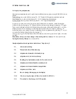
Adjustments and operation instructions, “Step by step” for super-users
3.11
LAME
3.12
Calibration of the Uout measurement
3.13
Control of the transformer tapping
3.11 LAME
Conditions for correct adjustment:
All light intensity steps have been adjusted
All lamps, connectors and isolating transformers in the circuit are OK
All isolating transformers are identical. If not, the smaller one should be used for the
adjustments.
OBS:
If for any reason, a LAME adjustment is not necessary on a circuit, a Learn procedure for Z, see
section c, must be performed.
Principle
The idea behind the built-in adjustment procedure is, that the CCR as a start learns the electrical
parameters in the circuit with all lamps OK, and after that the same with a number of faulty lamps.
The procedure must be performed as a minimum with all lamps OK, but the accuracy will
increase with a learn procedure with more faulty lamps.
If there is a demand for a high degree of accuracy with a high number of faulty lamps, a learn
procedure with 2, 3 or 5 faulty lamps can be performed, eventual followed by a correction with
one or more “Break-points”, f.i. 8 and/or 12 faulty lamps.
Normally a Learn procedure with 2 or 3 faulty lamps will be sufficient, as the CCR from the
learned data will calculate a higher number of faulty lamps.
We normally recommend a procedure as follows:
Learn procedure
with number of faulty lamps
Number faulty
lamps
0
1
2
5 (+ evt. 8,12)
= ”Break” Point
Minimal
Procedure
X
Normal
Procedure
X
X
X (3)
Procedure for
high accuracy
X X X X

