CCR961 MANUAL-GB
37
Version B2:01-07-2015
6
Remote Control
6.1
Standard RS485
The Mainboard includes all hardware and software for direct communication with a remote
control system via RS485. The connection in the cubicle is as standard a set of terminals (-XX1)
or a set of RJ45 connectors.
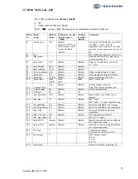
Description of the RS485 communication protocol:
General information:
19200 Baud, 8bit, no parity, 1 stop bit
CCR961 will only transmit after receiving a command or status inquiry.
Commands to CCR961.
1 2 3 4 5 6 7 8
9
10
11
Start ID-High
ID-Low
CMD Step RWY Mode Time
CRC
high
CRC
low
End
@
0..9
0..9 S,W
0..7 1..9
1..F
1..F 0..F 0..F *
Byte 1:
Start character @
Byte 2 and 3: CCR node number, decimal figure 0 - 32.
Byte 4:
Command = W. Status request = S
Byte 5:
Step command, decimal figure 0 - 7
Byte 6:
Circuit selector 1-4, not in use!
Byte 7:
Normal mode = 0. Service mode = 1, Not in use!
Byte 8:
Normal = 0. Set internal watch to 12.00 = 1
Byte 9 and 10 CRC hexadecimal figure between 00 and FF
Byte 11:
Stop character *
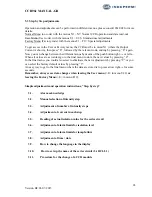
Back indications from CCR961:
1 2 3 4 5 6 7 8 9 10 11 12 13 14
Start ID-
High
ID-
Low
CMD Step RWY Err1 Err2 Sta Ana1 Ana2 Ana3 Ana1 Ana2
# 0 0 S,W 0..7 1..9 0..F 0..F 0..F
0..F 0..F 0..F 0..F 0..F
15 16 17 18 19 20 21 22
23 24
Ana3 Ana1 Ana2 Ana3 Ana1 Ana2 Ana3 CRC
High
CRC
low
End
0..F 0..F 0..F 0..F
0..F 0..F
0..F
0..F 0..F *
Byte 1 :
Start character #
Byte 2 and 3: CCR node number, decimal figure 0 - 32.
Byte 4:
Answer to command = R. Answer to status request = S
Byte 5:
Step indication, decimal figure 0 - 7
Byte 6:
Circuit selector 1-4, not in use!
Byte 7:
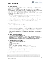
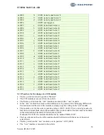
Error status 1: sum (0-F) of Lamp1 = 1, Lamp2 = 2, Emin1 = 4, Emin2 = 8
Byte 8:
Error status 2: sum (0-3) of Imin = 1, Imax = 2
Byte 9:
Key switch position: Remote = 2, Off or local = 0

