background image

CCR961 MANUAL-GB


44 

Version B2:01-07-2015 

U-out: 

Step = 2 
Profibus master will send flg. data bit to CCR: 
PA: 00000010 

step 2 

PB: 01010001 

master, tx analog value type 2 ~ Uout 

 
Profibus module will send flg. data bit to master: 
PC: 00110000 

48 ~ Uout = 0.48KV 

PD: 10100000 

analog value type 2 ~ Uout 


ISO value (E): 

Step = 2 
Profibus master will send flg. data bit to CCR: 
PA: 00000010 

step 2 

PB: 01110001 

master, tx analog value type 3 ~ ISO 

 
The isolation value is given in K

 by means of 3 digits: 2 significant number of zero’s 

(factor 10) 
The value is displayed as a binary value on port C + the first 4 bits in port D. 
 
Example 15K

: 1 5 0 = 0000 1001 1001 

 
Profibus module will send flg. data bit to master: 
PC: 10010110 

150 

PD: 10110000 

analog value type 3 ~ ISO 


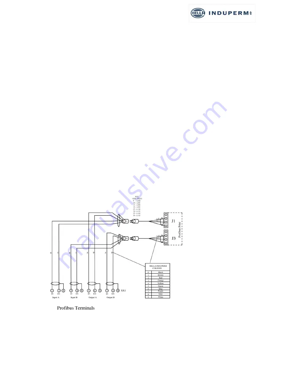
Connection diagram for Profibus to the terminals –XX1. 


Summary of Contents for CCR 961-SW4.00

Page 1: ...Regulator type CCR 961 SW4 00 USER MANUAL GB...

Page 2: ...4 The menu s 16 3 5 Power Transformer 17 4 CCR installation 18 4 1 Unpacking the CCR shipment 18 4 2 Before the installation 18 4 3 CCR installation 18 5 Commissioning 21 5 1 Preparation 21 5 2 Contr...

Page 3: ...nce of the CCR as well as for purchase of spare parts 1 3 Manufacturer information The CCR 961 are developed and manufactured by HELLA INDUPERM A S K benhavnsvej 1 DK 4800 Nyk bing Falster DENMARK Tel...

Page 4: ...3A 10A and 20A versions as well Standard input voltages are 230V 400V 10 50Hz or 60Hz 2 Hz Features Seven individual adjustable intensity steps Earth fault supervision with two alarm levels Lamp supe...

Page 5: ...ng transformer 2 2 0 25A Series circuit current nominal 13 2A current measuring transformer 13 2 0 25A All SW version can be supplied for a number of different languages The Danish and English languag...

Page 6: ...ponent failure is proven 3 CCR DESCRIPTION 3 1 General Information Hella Induperm Constant Current Regulator type CCR 961 is developed specially for the supply of power to lighting systems in airports...

Page 7: ...corresponding to the impedance in the series circuit The current transformer measures the value of the current in the series circuit and the measuring signal is send back to the CCR Module In the CCR...

Page 8: ...communication with the front panel Local operation or with the Remote Control The Main Board includes facilities for directly remote control in our RS485 serial protocol If Profibus is required an add...

Page 9: ...CCR961 MANUAL GB 9 Version B2 01 07 2015...

Page 10: ...in adjustable limit a CCR failure is properly at hand This is dangerous for the lamps and therefore the CCR is switched off and an I max is displayed in the menu and send to the remote control system...

Page 11: ...The number of faulty lamps can be detected up to 20 lamps with a very high accuracy Two alarm levels can be set The regulation circuit In the regulation circuit the actual current value is constantly...

Page 12: ...he CCR cubicle and communicates with the module though our RS485 serial communication If parallel interface to a remote control system is requested a Parallel interface module is placed in the CCR cub...

Page 13: ...CCR961 MANUAL GB 13 Version B2 01 07 2015...

Page 14: ...is active A flash every two seconds indicates that the earth error measuring is disconnected permanently GREEN The light in the green diode means that the actual current in the serial circuit is equa...

Page 15: ...he regulator Back indications alarms and analogue values will however still be send to the remote control system When you switch from Remote control mode to Manual control mode you have to pass the Tu...

Page 16: ...pecial function N1 Series circuit name Actual output current Actual selected intensity step Remote Off local operation selected Press Lower text line shows 10 500 XXX where XXX is the actual trigger f...

Page 17: ...connected in parallel so each winding only have to be calculated for 50 of the nominal primary current It is possible to change the primary windings from parallel to series if the following conditions...

Page 18: ...tput transformer and the CCR cubicle can be removed from the pallet 4 2 Before the installation Check the planned installation location The floor must be stable and the CCR cubicle must be fastened to...

Page 19: ...CCR961 MANUAL GB 19 Version B2 01 07 2015 CCR front view...

Page 20: ...r RS485 can be by means of terminals or RJ45 plugs Input power cable dimension must be according to calculated max input current Series circuit cables must be connected by means of cable shoes and the...

Page 21: ...is switched on No blinking must occur in the display The Key switch is turned to position Manual local operation C Setting and adjustments There are more menu areas Normal menu no access code needed w...

Page 22: ...tep after the set time in step 8 If time set 0s no automatic return will take place from step 8 U13 No of Steps 5 No of active steps to be set U14 Uout calibration Uout calibration Must be performed a...

Page 23: ...peakmax 10 0Ap Default Default Ipeak value during Soft Start F11 I peak limit 4100 OFF 4100 Off 4000 Max Value 4100 F12 Z engage delay 0 6s Default Default Z delay during switch on Note F14 must be a...

Page 24: ...by pressing E In the final menu you could also select to eliminate the new adjustments by pressing C or you can select the factory default values by pressing 5 An easy way to get to the final menu wh...

Page 25: ...cription disappear in the CCR display The Key switch is turned to the position Manual Switch on the CCR in step 1 by pressing 1 while observing the current value in the display If the CCR is not worki...

Page 26: ...ress E Enter the code for User Menu Press E Press 6 times to see Circuit Isolation Alarm 1 in the display Use to select the isolation value for the Alarm 1 limit Press once to see Circuit Isolation Al...

Page 27: ...to the menu for Store data Press E 3 9 How to change the language in the display The Key switch is turned to position Manual Press E Enter the code for User Menu Press E Press 18 times to see Language...

Page 28: ...uttons to choose the XXXX term Press E Press push buttons to select the Z1 value Press E Press push buttons to select the Z2 value Press E Press push buttons to select the Z3 value Press E Press push...

Page 29: ...7 C ASCII Latin Capital Letter C 068 D ASCII Latin Capital Letter D 069 E ASCII Latin Capital Letter E 070 F ASCII Latin Capital Letter F 071 G ASCII Latin Capital Letter G 072 H ASCII Latin Capital L...

Page 30: ...Letter U 118 v ASCII Latin Small Letter V 119 w ASCII Latin Small Letter W 120 x ASCII Latin Small Letter X 121 y ASCII Latin Small Letter Y 122 z ASCII Latin Small Letter Z 3 11 Procedure for the ch...

Page 31: ...justments OBS If for any reason a LAME adjustment is not necessary on a circuit a Learn procedure for Z see section c must be performed Principle The idea behind the built in adjustment procedure is t...

Page 32: ...he CCR will automatically run through all active steps 8 When the question 1 lamp pops up remove one lamp in the circuit and press E 9 When the question 2 lamp pops up press C shortly 10 Press 8 for B...

Page 33: ...the stored values in the tables The Ua value will increase when lamps gets faulty Table values can be seen in the User menu U2 E Enter code for User Mode E Press 2 Step 1 Step 2 Step 3 Table 0 100 10...

Page 34: ...t we have to calibrate Uout when the transformer tapping has been changed The factory setting is for the output transformer in 100 tapping The Key switch is turned to position Manual Press E Enter the...

Page 35: ...anging the maximum output power of the CCR by connecting the series circuit to a lower secondary output tapping than the maximum From factory the CCR s will always be shipped connected to full output...

Page 36: ...CCR961 MANUAL GB 36 Version B2 01 07 2015...

Page 37: ...Step command decimal figure 0 7 Byte 6 Circuit selector 1 4 not in use Byte 7 Normal mode 0 Service mode 1 Not in use Byte 8 Normal 0 Set internal watch to 12 00 1 Byte 9 and 10 CRC hexadecimal figur...

Page 38: ...low 9 57 112 57 73 Command W 87 73 87 30 Step 3 51 30 51 45 RWY 1 49 45 49 28 Mode 0 48 28 48 44 Time 0 48 44 48 28 28 decimals 1C Hex 1 2 3 4 5 6 7 8 9 10 11 Start ID High ID Low CMD Step RWY Mode Ti...

Page 39: ...on terminals XX1 for RS485 based remote control communication with the above described protocol In the lower part of the picture is shown that upon request the terminals XX1 can be exchanged to two n...

Page 40: ...e if the Master bit is 1 from both channels If the Master bit in both channels is permanently set to 1 and there is a failure on one Chanel there is a risk that the communication will fail as no shift...

Page 41: ...71H 6 analog pointer 1 7 analog pointer 2 TO master IM184 Bit Port PC 0 Step bit 0 1 Step bit 1 2 Step bit 2 3 4 5 6 7 Lamp error 1 PD 0 Lamp error 2 1 E min1 2 E min2 3 I min 4 I max 5 Remote 6 7 0...

Page 42: ...4 5 6 The analog value is given as follows 1 Iout Lamp failure and Uout Value is given only in PC Bit 7 6 5 4 3 2 1 0 Binary value 128 64 32 16 8 4 2 1 Iout Binary value 10 Iout A Uout Binary value 10...

Page 43: ...x alarm Profibus master will send flg data bit to CCR PA 00000010 step 2 PB 00000001 master Status req Profibus module will send flg data bit to master PC 00000000 PD 00110000 remote Imax alarm Analog...

Page 44: ...E Step 2 Profibus master will send flg data bit to CCR PA 00000010 step 2 PB 01110001 master tx analog value type 3 ISO The isolation value is given in K by means of 3 digits 2 significant digits num...

Page 45: ...3 Parallel control When a parallel interface is required a separate parallel interface board is placed in the CCR cubicle and this board will communicate with the CCR module via the RS485 serial bus...

Page 46: ...rs are designed for max 1mm2 flexible wire If heavier wire is used we can offer a solution with 25 nos terminals for 2 5mm2 cable This row of terminals is mounted in the front of the CCR for easy acce...

Page 47: ...on is similar to the solution for Parallel control by mounting a special box in the CCR cubicle that will convert the IP communication to RS485 towards the CCR The Protocol and set up for this solutio...

Page 48: ...n Board and on the Profibus Board only for Profibus solutions The drawing below shows the setting of the dip switches both on the Main Board and on the Profibus Board In solutions with a parallel remo...

Page 49: ...ized FAA high voltage male connector in one end The other end is connected to the series circuit on the lightning arrestors Function In normal operation are the two male plugs mounted in the upper fem...

Page 50: ...7 2 Key operated safety type When the key is turned the front of the Cut out devise with its high voltage connector can be pulled out and turned 180 to change the function THE CUT OUT DEVICE MUST ONLY...

Page 51: ...Imax alarm is adjusted to 5 1A The CCR is switched on in the lowest step wait some seconds and the switch to the highest step The CCR must switch off with Imax alarm within app 4 sec Every 5 years The...

Page 52: ...circuit due to selector switch or single lamp control Adapt 8 Flash over on Lightning Arrestors Change Lightning Arrestors 9 Display saying Memory Board missing in CCR Module 10 Default values Memory...

Page 53: ...961 V4 961555 14 Tool set CCR 961 incl 961360 961361 15 Cable 961 current measurement 961400 16 Monitor Kit Diagram cable Dongle 961 MON 17 Lightning arresstor 1 2KV 30gr 29 150 211 18 Lightning arres...

Reviews: