Gear Blind OS 58/56
Subject to technical modifi cations - Date 06/2006
15
Type: AF 100
Tender Specifi cation
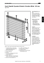
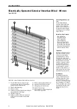
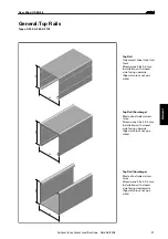
Top Rail
U-shaped moulded cold roll profi le, galvanised and bordered
on both edges; dimensions 58 x 56 mm. For a surcharge, top
rail with extruded aluminium, dimensions 59 x 59.5 mm, if
requested (cutting edges without surface treatment).
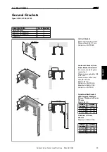
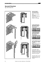
Installation with galvanised steel brackets and integrated
fi xing device for cover to discreetly hide the clamps of the
protection.
Bottom Rail
Extruded, closed aluminium profi le, powder-coated or natural-
ly anodised.
Dimensions 100 x 18.6 mm.
Closed with plastic end caps.
Slats
Slightly curved aluminium slats made from highly elastic
special alloy, bend proof, scratchproof and shockproof, 2-layer
stove enamelled (incl. on the longitudinal edges); slat width
100 mm, slat thickness 0.44 mm.
Slat Guides (Wind Protection Device)
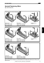
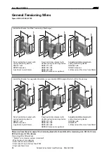
Standard: low-noise “stable” wire tension system made from
braided fl at tape, UV-protected, Dimensions 4.5 x 1.5 mm. For
a surcharge, alternative: wire tension, polyamide-coated steel
cord, polyamide-coated stainless steel cord or shiny stainless
steel cord, if requested. All variations dimensions: ø 3 mm.
Punched through the ends of all the slats, stretched taught
using a wire bracket of die-cast aluminium with nipple.
Tilting Device
Standard: tilting device without a working position with tilting
both ways. When lowering the blind, it is closed towards the
outside, smooth tilting process when changing direction of
movement, when raising the blind, it is closed on the inside.
For a surcharge, if requested, (or standard at AF 100L): Vario-
tec-bearing with working position. The blind is in the shading
position when lowered (approx. 50°), when it reaches the bot-
tom end position the blind closes completely, smooth tilting
process when changing direction of movement, blind raises
horizontally. (Adjustable and lockable with a short upwards
motion at any height).
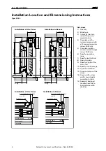
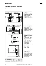
Side Guide Rails
Extruded aluminium profi le with anti-noise plastic insert.
Dimensions: 20/27, 27/27, 30/80, 30/17, 18/20.
Installation with adjustable die-cast aluminium brackets,
distance as required according to documentation, or laterally
into the wall-clearance, with the option of being buried or
visible.
Round extruded aluminium side guide rails ø 45 with anti-
noise plastic insert.
Installation standard with adjustable brackets consisting of a
powder-coated die-cast aluminium distance bracket and die-
cast zinc Collinox-coated clamping lock.
Ladder Cord
High-strength shrink-resistant terylene-polyester.
For a surcharge with transverse tensioning, linked to every
slat non-positively (double Omega-punching), if requested.
Lifting Tape
Anti-friction coated lifting tapes for a run with minimum wear
and tear and maximum UV-protection, dimensions 6.0 x 0.28
mm, tear-proof at 750N, guaranteed thickness tolerance in the
range of 1/100 mm.
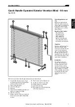
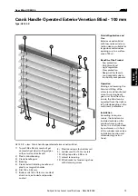
Crank Handle Operation
Raising and lowering the blind and repositioning the slats
using a crank handle. Maintenance-free bevel gear unit with
gear reduction 2:1, duct into the interior via bearing, powder-
coated aluminium crank handle rod with folding handle and
crank holder. For a surcharge, end stops at the top and bottom
via limit stop, if requested.
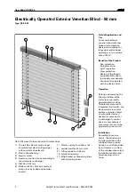
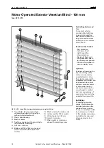
Electric Drive
Raising and lowering the blind and repositioning the slats
using an electric motor (230 V/AC). Drive with integrated
planetary gear, limit switch at the top and bottom, thermo-pro-
tection switch to prevent overloading the motor. Tilting of the
slats is enabled by lightly touching the switch in the respec-
tive direction. If several motors should be activated with one
switch, a control unit is necessary.
Protection Cover, Half-Box, Whole-Box
Technical description in the tender specifi cation “Boxes and
Covers”.
Ext
er
ior
V
enetian Blind
10
0

