US
DE
Automation Instructions CPK • 10-2015 •106-29009
Program interface
29
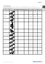
7 .7 Accessories
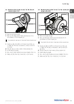
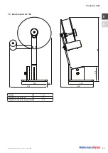
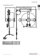
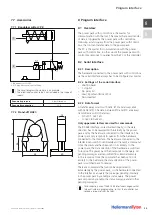
7 .7 .1 Bandoleer cutter CPK
1
2
1 Bandoleer cutter CPK
2 3/2-way directional-control valve
The circuit diagram shown here is an example.
The directional-control valve is not included in the scope of
supply.
Pneumatic pressure
6 bar, filtered air
Pneumatic connection
PK-4
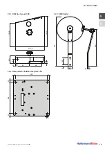
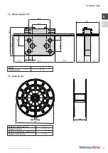
7 .7 .2 Stand-off HH20
45
40
13
55
24
8 Program interface
8 .1 Overview
The power pack with control box is the master for
communication with the tool. This means that every transfer
of data is triggered by the power pack with control box.
Following a status query from the power pack with control
box, the tool can transfer data to the power pack.
The PC is the master for communication with the power
pack with control box, in other words the power pack with
control box responds to queries from the PC or the controller.
8 .2 Serial interface
8 .2 .1 Description
The hardware connected to the power pack with control box
via the serial interface always has to be configured as master.
8 .2 .2 Settings of the serial interface
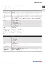
• 256000 baud
• 1 stop bit
• No parity bit
• Least Significant Bit sent first
• Non-inverted
8 .2 .3 Data format
A transfer always starts with 0x02 (STX) and always ends
with 0x03 (ETX). The data between STX and ETX are always
transmitted as ASCII characters:
• 0: 0x30 1: 0x31 etc.
• A: 0x41 B: 0x42 etc.
Only uppercase letters are used for commands .
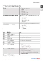
The RS-485 interface is used bi-directionally, so the data
direction has to be reversed both internally by the power
pack and by the hardware connected to the interface. The
power pack only responds to queries from the hardware
connected to the interface. The hardware connected to the
interface can switch to send mode and transmit a command.
Once the command has been sent in its entirety to the
power pack, the data direction of the hardware is switched
to receive. The power pack then responds to the query. All
pending messages are transmitted from internal memory
in this response. Once the command has been sent in its
entirety to the hardware, the data direction of the power
pack is switched back to receive.
There are commands that cannot be responded to
immediately by the power pack, so the hardware connected
to the interface can query the messages pending internally
in the power pack by sending a status query. The power
pack responds by sending the status message and all other
pending messages.
For bi-direction use of the RS-485 interface changeover has
to be activated in programming, so that the controller can
receive a response from the tool.
Summary of Contents for Autotool 2000 CPK
Page 1: ...A u t o t o o l 2 0 0 0 TOC Cover Automation Instructions Automatisierungsanleitung...
Page 2: ...2 US English DE Deutsch Automation Instructions 3 Automatisierungsanleitung 37...
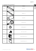
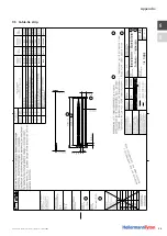
Page 36: ...US DE Automation Instructions CPK 10 2015 106 29009 Appendix 36 9 5 Cable tie strip...
Page 70: ...US DE Automatisierungsanleitung CPK 10 2015 106 29009 Anhang 70 9 5 Bandkette...
Page 71: ......

