Helmer Scientific i.Series
®
and Horizon Series
™
Freezer - Undercounter
Service and Maintenance Manual
360417/A
10
Install / Replace Chart Paper
Notes
• For accurate temperature reading, ensure the current time is aligned with the time line groove when the chart knob is
fully tightened.
• Contact Helmer Customer Service or your distributor to reorder chart paper.
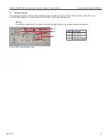
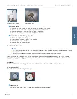
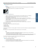
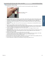
Chart recorder stylus and time line groove
1. Press and hold the
C
button. When the stylus begins to move left, release the button. The LED flashes.
2. When the stylus stops moving, remove the chart knob then move the knob up and away.
3. Place chart paper on the chart recorder.
4. Gently lift the stylus and rotate the paper so the current time line corresponds to the time line groove.
5. Hold the chart paper in place while making sure the chart knob is fully tightened.
(Failure to fully tighten the knob can result in paper
slipping and losing time.)
6. Press and hold the C button. When the stylus begins to move right, release the button.
7.
Confirm the stylus is marking on the paper and stops at the correct temperature.
8. Calibrate the chart recorder to match the primary temperature if needed and close the recorder door.
External Monitoring Devices
The remote alarm interface is a relay switch with three terminals:
♦
Common (COM)
♦
Normally Open (NO)
♦
Normally Closed (NC)
Terminals are dry contacts and do not supply voltage. The interface circuit is either normally open or normally closed, depending on
terminals used.
Requirements for your alarm system determine which alarm wires must connect to terminals.
•
The interface on the remote alarm monitoring system is intended for connection to the end user’s central alarm
system(s) using normally-open or normally-closed dry contacts.
•
If an external power supply exceeding 33 V (RMS) or 70 V (DC) is connected to the remote alarm monitoring system’s circuit,
the remote alarm will not function properly and may cause damage to the control board or result in injury to the user.
The terminals on the remote alarm interface have the following maximum load capacity:
♦
115V or 230V: 1 A at 33 V (AC) RMS or 30 V (DC)
Connect to Remote Alarm Interface
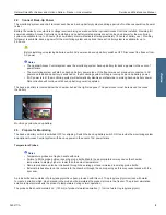
1. On the back of the freezer, locate the remote alarm terminals.
2. Connect the remote alarm wires to the appropriate terminals, according to the requirements for your alarm system.
3. Use a cable tie to relieve strain on the alarm wires (as necessary).
i.Series


