background image

Helmer Scientific i.Series

®

 and Horizon Series

 Freezer - Undercounter

Service and Maintenance Manual 

360417/A

70

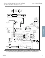
15.2  HBF and HPF Models (without Access Control)

Horizon Series

Summary of Contents for HBF105-GX

Page 1: ...D E Freezer Service and Maintenance Manual i Series and Horizon Series Undercounter 360417 A Laboratory i Series iLF105 GX Horizon Series HLF105 GX Plasma Storage i Series iBF105 GX Horizon Series HBF...

Page 2: ...ted States of America All other trademarks and registered trademarks are the property of their respective owners Helmer Inc doing business as DBA Helmer Scientific and Helmer Disclaimer This manual is...

Page 3: ...al Adapter Kits for Medication Dispensing Locks 12 2 8 Reverse Door Hinges and Handle 13 3 Controls 17 3 1 Home Screen and Screensaver 17 3 2 Home Screen Functions 17 3 3 Alarm Reference 17 3 4 Settin...

Page 4: ...52 10 2 Alarm Reference 54 10 3 Settings 55 11 Maintenance 58 11 1 Alarm Tests 59 11 2 Test and Replace Back up Batteries 60 11 3 Check Probe Bottle 61 11 4 Upper and Lower Door Hinge Cams 61 11 5 Cl...

Page 5: ...nstalled and used in accordance with the instruction manual may cause harmful interference to radio communications Operation of this equipment in a residential area is likely to cause harmful interfer...

Page 6: ...aution when adding and removing product from the freezer Do not open multiple loaded drawers at the same time Use only a manufacturer supplied power cord Avoid risk of ignition by using only manufactu...

Page 7: ...tion label located on the rear of the freezer toward the bottom left corner The model also appears on a label located in the chamber on the upper right side wall Note Information contained in this spe...

Page 8: ...is required Do not sit lean push or place heavy objects on top surface Do not lean on or push down on an open door or extended drawers To avoid damaging refrigerant tubing or risking refrigerant leak...

Page 9: ...monitoring system will automatically disable some features to prolong back up battery power Data collection will continue until back up battery power is depleted The back up battery is located below t...

Page 10: ...Recorder if included Note If the chart recorder has been operating on battery power the battery should be replaced to ensure the back up source has proper charge For complete information refer to the...

Page 11: ...recorder to match the primary temperature if needed and close the recorder door External Monitoring Devices The remote alarm interface is a relay switch with three terminals Common COM Normally Open...

Page 12: ...nsure a minimum of 2 50 mm clearance is provided below the fan Drawers Remove Drawer 1 Pull the drawer out until it stops 2 Lift the front of the drawer off the front rollers on the slide 3 With the f...

Page 13: ...d to engage with brackets 3 Pulling the shelf forward gently the shelf should not disengage from the rear brackets Move Shelf Brackets 1 Using a screwdriver remove the bracket retainers 2 Tap the brac...

Page 14: ...ecommends two people for this procedure Remove Door and Hinges 1 Press and release the door to open the access panel Switch the AC power switch to OFF and switch the back up battery switch to OFF 2 Di...

Page 15: ...e door 10 Using a 2 Phillips screwdriver remove the two screws attaching upper and lower hinges to the door and set aside 11 Using a 2 Phillips screwdriver remove the three screws securing the upper a...

Page 16: ...witch wires along with the display power and communication cables to the zip tie holder using a zip tie 9 Reroute the display power and communication cables along the inside edge of the door and throu...

Page 17: ...et so the door can open and close without straining cables Install the grommet in the access panel 8 Attach the door handle on the opposite side of the door with four screws 9 Attach the strike plate...

Page 18: ...ens View current interior cabinet temperature readings View current system time and date Access any of the five home screen applications touch i C APPS for additional applications View information abo...

Page 19: ...hanging temperature settings affects operation of the freezer Do not change settings unless instructed in product documentation or by Helmer Technical Service The i C temperature monitor and controlle...

Page 20: ...mperature other than 30 0 C Change Temperature Setpoint 1 Touch i C APPS Settings 2 Enter the Settings password 3 Touch the minus or plus on the Temperature Setpoint spin box to select the desired val...

Page 21: ...efrost event s or Toggle the Start Stop button The Defrost icon will appear for the duration of the defrost cycle 3 Touch the corresponding Time spin box to set the starting time for each defrost even...

Page 22: ...downloaded but doing so will not free up capacity SD card replacement recommended Drive Space Full Triggered if the SD card containing downloadable historical data has reached its capacity No new data...

Page 23: ...he appropriate password If viewing settings for the first time enter the factory default password of 1234 Offset values are adjusted to the tenth of a degree 0 1 After one hour of no interaction the H...

Page 24: ...g Saved appears next to the spin box 11 Remove the thermometer from probe 12 Replace and secure the bottle cap ensuring a tight fit 13 Place the probe in the bottle immersing at least 2 50 mm Control...

Page 25: ...tting Restored Value Home Screen Application Icons i C APPS Settings Temperature Graph Temperature Alarm Test Information Logs Display Brightness High level 3 Password for Settings screen 1234 Sounds...

Page 26: ...Upper Rail 0 7 C Lower Rail 0 7 C Delay on Start Up 2 minutes Speed During Probe Error 50 Restore Settings 1 Touch the Settings icon 2 Scroll down and touch the Restore Factory Settings button The Re...

Page 27: ...Replace monitoring system back up battery Examine probe bottle and clean or replace if necessary Check the solution level in the probe bottle Refill or replace if necessary Lubricate door cams in bot...

Page 28: ...vent Log Touch the event to view event details 8 Observe the temperature at the time of the low temperature alarm event Compare this to the alarm setpoint Test the High Alarm 1 Identify the current se...

Page 29: ...n solution 8 Place the monitor probe in the probe bottle immersing it at least 2 50 mm Power Failure Alarm Test Note During a power failure the power failure alarm sounds and the battery provides powe...

Page 30: ...power switch ON Remove and Replace Battery Take care not to short the battery terminals to the bracket or to each other when removing or attaching terminal connectors bracket or bracket screws 1 Swit...

Page 31: ...apply grease 5 Press the hinge covers into place to reinstall 4 5 Display Board Battery NOTICE The display board is sensitive to static electricity and can be damaged by electrostatic discharge Use p...

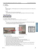
Page 32: ...ll using a soft brush and a vacuum cleaner Door Gasket Clean with a soft cloth and mild soap and water solution Probe Bottle Clean and Refill Probe Bottle 1 Remove all probes from the bottle 2 Remove...

Page 33: ...oler cover and drain port Drain tube and heating element Remove Unit Cooler Cover 1 Switch the AC power switch OFF Switch the back up battery switch OFF 2 Remove the top drawer or shelf from the cabin...

Page 34: ...aligned with the unit cooler drain spout inside the chamber 4 Attach the drain tube to the unit cooler drain spout 5 Insert the drain line heater in the drain tube at an upward angle The black heating...

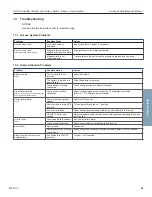
Page 35: ...obe connection Test resistance of probe 86 to 110 Replace probe if needed Power failure alarm Power was interrupted to freezer Restore facility power Power switch is in the off o position Turn power s...

Page 36: ...e shelves against back wall Temperature setpoint was adjusted Check temperature setpoint and temperature settings Change to default settings or desired setpoint Control probe is reading too high low C...

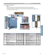
Page 37: ...play assembly Letter Description Part Number Volts Letter Description Part Number A Temperature chart recorder 500613 1 115 D Display assembly 800041 1 500616 1 230 E Battery key switch optional Acces...

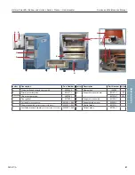
Page 38: ...monitor probe 800038 1 H Evaporator assembly 801046 1 Not shown Chart recorder probe 400799 1 I Evaporator cover heater 801077 1 115 C Door gasket 321200 1 801078 1 230 D Full shelf includes hardware...

Page 39: ...roper ESD precautions when handling board Letter Description Part Number Volts Letter Description Part Number Volts A i C3 power supply board 800916 1 I Drain line heater 402301 1 115 B i C3 control b...

Page 40: ...Helmer Scientific i Series and Horizon Series Freezer Undercounter Service and Maintenance Manual 360417 A 39 8 Schematics 8 1 iBF and iLF Models i Series...

Page 41: ...Helmer Scientific i Series and Horizon Series Freezer Undercounter Service and Maintenance Manual 360417 A 40 i Series...

Page 42: ...d Do not sit lean push or place heavy objects on top surface Do not lean on or push down on an open door or extended drawers To avoid damaging refrigerant tubing or risking refrigerant leak use cautio...

Page 43: ...p battery is located below the chamber behind the front access panel The right side panel cover must be removed to access the optional Access Control back up battery Monitoring system back up battery...

Page 44: ...t the battery to provide the monitoring system with back up power in the event of an AC power failure If included switch the Access Control back up battery ON to provide the optional Access Control sy...

Page 45: ...or complete information refer to the Temperature Chart Recorder Operation and Service Manual The chart recorder has a back up battery system enabling a period of continuous operation if power is lost...

Page 46: ...recorder to match the primary temperature if needed and close the recorder door External Monitoring Devices The remote alarm interface is a relay switch with three terminals Common COM Normally Open N...

Page 47: ...sure a minimum of 2 50 mm clearance is provided below the fan Drawers Remove Drawer 1 Pull the drawer out until it stops 2 Lift the front of the drawer off the front rollers on the slide 3 With the fr...

Page 48: ...ge with brackets 3 Pulling the shelf forward gently the shelf should not disengage from the rear brackets Move Shelf Brackets 1 Using a screwdriver remove the bracket retainers 2 Tap the brackets upwa...

Page 49: ...recommends two people for this procedure Remove Door and Hinges 1 Press and release the door to open the access panel Switch the AC power switch to OFF and disconnect the back up battery 2 Disconnect...

Page 50: ...Using a 2 Phillips screwdriver remove the two screws attaching upper and lower hinges to the door and set aside 11 Using a 2 Phillips screwdriver remove the three screws securing the upper and lower h...

Page 51: ...tch wires along with the display power and communication cables to the zip tie holder using a zip tie 10 Reroute the display power and communication cables along the inside edge of the door and throug...

Page 52: ...without straining cables Install the grommet in the access panel 8 Attach the door handle on the opposite side of the door with four screws 9 Attach the strike plate to the opposite side of the unit...

Page 53: ...icates when freezer door is open D Temperature Unit Indicator Indicates temperature reading is in C or F E Display Displays real time temperature information setpoints and alarms F MODE button Allows...

Page 54: ...oes not display the time at which a minimum or maximum temperature occurred The maximum period of time the timer can record is 99 59 99 hours and 59 minutes Press and hold either the Up or Down Arrow...

Page 55: ...FF alarm an Er05 error can be expected as a result of the absence of power to the compressor inverter Table 11 Alarm Indications Alarm Alarm Type Visual Indicator High Temperature Primary Monitor Prob...

Page 56: ...0 C Monitor Offset MONITOR Lamp only 10 0 to 10 0 C 18 to 18 F Varies Control Offset CONTROL Lamp only 10 0 to 10 0 C 18 to 18 F Varies Evaporator Defrost Offset MONITOR lamp CONTROL lamp 10 0 to 10 0...

Page 57: ...ure measured by a calibrated reference thermometer If the primary monitor probe is not reading correctly change the monitor offset value displayed Notes Ensure the product simulation bottle is full of...

Page 58: ...ure is 29 2 Average monitor temperature is 31 2 Current Control Offset is 0 3 Current Control Offset is 0 3 Subtract 29 2 30 0 0 8 difference between average temperature and setpoint Subtract 31 2 30...

Page 59: ...rature calibration on the monitor and change it if necessary Replace monitoring system back up battery Examine probe bottle if installed and clean or replace if necessary Check the solution level in t...

Page 60: ...simulation solution 5 Observe the temperature on the monitoring system display at which the high temperature alarm sounds 6 Compare the temperature at which the alarm sounds to the high alarm setpoint...

Page 61: ...place Battery Take care not to short the battery terminals to the bracket or to each other when removing or attaching terminal connectors bracket or bracket screws 1 Switch the battery back up switch...

Page 62: ...grease 5 Press the hinge covers into place to reinstall 11 5 Clean the Freezer Cabinet Exterior Clean exterior surfaces with a soft cotton cloth and non abrasive liquid cleaner Cabinet Interior Clean...

Page 63: ...nit cooler cover and drain port Drain tube and heating element Remove Unit Cooler Cover 1 Switch the AC power switch OFF Switch the back up battery switch OFF 2 Remove the top drawer or shelf from the...

Page 64: ...d with the unit cooler drain spout inside the chamber 4 Attach the drain tube to the unit cooler drain spout 5 Insert the drain line heater in the drain tube at an upward angle The black heating eleme...

Page 65: ...eck wiring and replace battery if needed Probe failure alarms Er01 Control Probe Er02 Monitor Probe Er03 Evaporator Defrost Probe Faulty probe or wiring connection Check corresponding probe connection...

Page 66: ...helves against back wall Temperature setpoint was adjusted Check temperature setpoint and temperature settings Change to default settings or desired setpoint Control probe is reading too high low Chec...

Page 67: ...hart recorder 500613 1 115 E Membrane 370225 1 500616 1 230 Not shown Control Monitor interface cable 401796 1 Not shown Chart paper 52 sheets 220419 F Access Control keypad 800007 1 Chart recorder ba...

Page 68: ...itor probe 801017 1 H Evaporator cover heater 801077 1 115 Not shown Chart recorder probe 400799 1 801078 1 230 C Door gasket 321200 1 I Evaporator assembly 801046 1 D Full shelf includes hardware 401...

Page 69: ...discharge Use proper ESD precautions when handling the board Letter Description Part Number Volts Letter Description Part Number Volts A Back up battery optional Access Control 121018 H Condensing Uni...

Page 70: ...Helmer Scientific i Series and Horizon Series Freezer Undercounter Service and Maintenance Manual 360417 A 69 15 Schematics 15 1 HBF and HLF Models Horizon Series...

Page 71: ...Helmer Scientific i Series and Horizon Series Freezer Undercounter Service and Maintenance Manual 360417 A 70 15 2 HBF and HPF Models without Access Control Horizon Series...

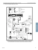
Page 72: ...Helmer Scientific i Series and Horizon Series Freezer Undercounter Service and Maintenance Manual 360417 A 71 15 3 HBF and HLF Models with Access Control Horizon Series...

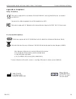
Page 73: ...ce This device complies with the 2011 65 EU Directive for the Restriction of Hazardous Substances RoHS This device falls under the scope of Directive 2102 19 EU Waste Electrical and Electronic Equipme...

Page 74: ...ar Helmer will cover repair labor costs including travel and the cost of refrigerant and supplies necessary to perform authorized repairs Repair service must be performed by an authorized Helmer servi...

Page 75: ...Helmer Scientific i Series and Horizon Series Freezer Undercounter Service and Maintenance Manual 360417 A 74...

Page 76: ...Helmer Scientific 14400 Bergen Boulevard Noblesville IN 46060 USA Copyright 2021 Helmer Inc 360417 A...

Reviews: