background image

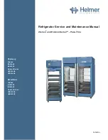
Helmer Scientific i.Series

®

 and Horizon Series

 Refrigerator - Pass-Thru

Service and Maintenance Manual 

360429/A

4

About this Manual

1.1 

Intended Audience

This manual provides information on i.Series

®

 and Horizon Series™ pass-thru blood bank and pharmacy refrigerators. It is 

intended for use by end users of the refrigerator and authorized service technicians.

1.2 

Model Reference

Models are indicated by a distinguishing model number that corresponds to the series, type, number of doors, and capacity of the 
refrigerator. For example, “iBR226-GX” refers to an i.Series Blood Bank refrigerator with two doors total (one door on the clean 
room side of the unit, and one door on the control side of the unit) and an approximate capacity of 26 cu ft.

1.3 

Intended Use

  Note

This equipment has been tested and found to comply with the limits for a Class A digital device, pursuant to part 15 of the 
FCC Rules. These limits are designed to provide reasonable protection against harmful interference when the equipment 
is operated in a commercial environment. This equipment generates, uses and can radiate radio frequency energy and, if 
not installed and used in accordance with the instruction manual, may cause harmful interference to radio communications. 
Operation of this equipment in a residential area is likely to cause harmful interference in which case the user will be required 
to correct the interference at his own expense.

Helmer refrigerators are intended for the storage of blood products and other medical and scientific products. 

1.4 

Safety Symbols and Precautions

Symbols found in this document

The following symbols are used in this manual to emphasize certain details for the user:

Task  

Indicates procedures which need to be followed.

Note 

 Provides useful information regarding a procedure or operating technique when using Helmer 

Scientific products

NOTICE

  Advises the user against initiating an action or creating a situation which could result in damage to 

equipment; person injury is unlikely.

Symbols found on the unit

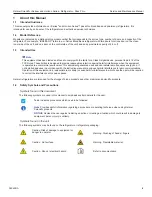
The following symbols may be found on the refrigerator or refrigerator packaging:

Caution: Risk of damage to equipment or 
danger to operator

Warning: Crushing of hands / fingers

Caution:  Hot surface

Warning: Flammable material

Caution:  Shock / electrical hazard 


Refer to documentation

Summary of Contents for HBR226-GX

Page 1: ...ervice and Maintenance Manual i Series and Horizon Series Pass Thru Pharmacy i Series iPR226 GX iPR458 GX Horizon Series HPR226 GX HPR458 GX Blood Bank i Series iBR226 GX iBR458 GX Horizon Series HBR2...

Page 2: ...d States of America All other trademarks and registered trademarks are the property of their respective owners Helmer Inc doing business as DBA Helmer Scientific and Helmer Disclaimer This manual is i...

Page 3: ...2 Home Screen Functions 13 3 3 Alarm Reference 13 3 4 Settings 14 3 5 Sensor Calibration 18 4 Maintenance 23 4 1 Alarm Tests 24 4 2 Test and Replace Backup Batteries 26 4 3 Check Probe Bottle if inst...

Page 4: ...Interface 45 10 2 Alarm Reference 47 10 3 Settings 47 11 Maintenance 51 11 1 Alarm Tests 52 11 2 Test and Replace Backup Batteries 53 11 3 Check Probe Bottle if installed 53 11 4 Clean the Refrigerat...

Page 5: ...ipment generates uses and can radiate radio frequency energy and if not installed and used in accordance with the instruction manual may cause harmful interference to radio communications Operation of...

Page 6: ...instructed Keep hands away from pinch points when closing the door Avoid sharp edges when working inside the electrical compartment and refrigeration compartment Ensure products are stored at recommen...

Page 7: ...t specification label on your unit for current values 1 7 Product Labels This information appears on the product specification label located on the top of the refrigerator next to the electrical box T...

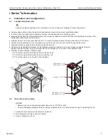
Page 8: ...eed additional clearance for the following scenarios placing a unit where hinges are against the wall placing units side by side using an optional trim kit on a single unit or on one or both adjacent...

Page 9: ...wer is depleted The backup battery and i Lock switch if installed are located on top of the refrigerator Removing the ventilated cover on the ante room control side allows access to the backup battery...

Page 10: ...ight seal Chart Recorder if included Note If the chart recorder has been operating on battery power the battery should be replaced to ensure the backup source has proper charge For complete informatio...

Page 11: ...battery is charged The LED indicator glows red continually when main power is functioning and the battery is either not installed or needs to be changed The LED indicator flashes red to indicate that...

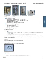
Page 12: ...mance of unit Drawers Remove Drawer 1 Use a 2 Phillips screwdriver to remove screw from each of four retaining clips total 4 screws 2 Use a 2 Phillips screwdriver to remove all screws total 8 securing...

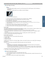
Page 13: ...nto chamber placing it on brackets 2 Gently bump front and rear edge of shelf downward to engage brackets 3 Ensure shelf does not disengage from brackets by gently pulling shelf forward Move Shelf Bra...

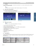
Page 14: ...t interior cabinet temperature readings View the current system time and date Access any of the five homescreen applications touch i C APPS for additional applications View information about current a...

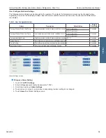
Page 15: ...settings affects operation of the refrigerator Do not change settings unless instructed in product documentation or by Helmer Technical Service The i C temperature monitor and controller is programme...

Page 16: ...requires a chamber temperature other than 4 0 C for iBR models or 5 0 C for iPR models 1 Touch i C APPS i C Settings 2 Enter Settings password 3 Touch minus or plus on Temperature Setpoint spin box to...

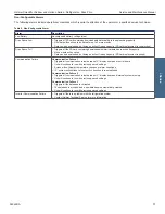
Page 17: ...5 5 C iBR models 0 minutes 6 5 C iPR models Primary Monitor Probe Low Temp Low temperature at which alarm condition occurs 1 5 C iBR models 0 minutes 2 0 C iPR models Compressor High Temp High tempera...

Page 18: ...a will be saved Data can be downloaded but doing so will not free up capacity SD card replacement required Communication Failure Communication Failure 1 Triggered if communication is lost between i C...

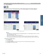
Page 19: ...s password protected enter the appropriate password If viewing settings for the first time enter the factory default password of 1234 Offset values are adjusted to the tenth of a degree 0 1 After one...

Page 20: ...rsed at least 2 50 mm 3 Place reference thermometer in available probe hole Tighten thumb screw until thermometer is secure Take care not to over tighten thumb screw 4 Close door and allow chamber tem...

Page 21: ...spin box 10 Touch minus or plus on corresponding spin box to increase or decrease value by value calculated in Step 6 New Setting Saved appears next to spin box 11 Remove thermometer from probe 11 Loo...

Page 22: ...Touch Sensor Calibration 4 Touch minus or plus on Control Probe Offset spin box Raise offset value to lower chamber temperature lower offset value to raise chamber temperature 5 Touch Home to return...

Page 23: ...ntained in real time clock Hour AM PM Language Not affected language previously selected during setup Temperature Units C Password Protection for Settings screen On Temperature Graph Screensaver On Li...

Page 24: ...nitor and change it if necessary Replace monitoring system backup battery Examine probe bottle s and clean or replace if necessary Check the solution level in the probe bottle s Refill or replace if n...

Page 25: ...s 7 Touch i C APPS Information Logs Event Log Touch event to view event details 8 Observe temperature at time of low temperature alarm event Compare this to alarm setpoint Test the High Alarm 1 Identi...

Page 26: ...warm water 6 Place primary monitor probe in probe bottle immersing at least 2 50 mm or place in ballast and secure with thumbscrew taking care not to overtighten Power Failure Alarm Test Note During a...

Page 27: ...nnect power wires from battery terminals 4 Using a 2 Phillips screwdriver remove two 2 screws securing battery strap to top of cabinet 5 Remove battery strap and set it aside 6 Remove battery from the...

Page 28: ...E Conductive grease reapplication is only necessary on the upper door hinge of i Series models and only for the door that has the i C3 display Use only conductive grease 1 Switch main power switch OFF...

Page 29: ...ive maintenance schedule Clean Condenser Grill 1 Switch main power switch OFF switch backup battery switch OFF disconnect AC power cord from power receptacle 2 Using a 2 Phillips screwdriver remove sc...

Page 30: ...p 1 Switch main power switch OFF switch backup battery switch OFF 2 Using a 2 Phillips screwdriver remove lamp strip from chamber wall 3 Disconnect wire from the first LED at top of strip and remove s...

Page 31: ...an 8mm socket wrench remove four screws securing the unit cooler cover 6 Carefully lower unit cooler cover to avoid damage to the fan wiring Install Unit Cooler Cover 1 Verify unit cooler wiring is c...

Page 32: ...is too warm or too cold Probe bottle is empty or probe is out of bottle or ballast Check the level of product simulation solution in the bottle Verify probe is fully inserted in bottle or ballast Pri...

Page 33: ...ature alarm is active Condenser fins are dirty Clean condenser coil Condenser probe is out of calibration Calibrate condenser probe Condenser probe is faulty Check condenser probe connection Test resi...

Page 34: ...els 4 door models 400862 1 400998 1 400862 2 B Door lock 220540 K Upper hinge assembly i Center display door includes pin and bracket Left hinge Right hinge 401897 2 067 C Caster 220467 401897 1 067 D...

Page 35: ...r fan motor 800995 1 H Chart recorder probe 800024 1 C Control probe 800048 1 I Primary monitor probe 800038 1 D Shelf Includes hardware 402385 1 069 J Probe bottle and glycerin kit 400922 1 E Two way...

Page 36: ...Description Model Part Number Letter Description Part Number Volt A Compressor 226 801101 1 I Lighting power supply 120624 458 801109 1 J Backup battery switch 120202 B Compressor Inverter 801102 1 K...

Page 37: ...MER INC Condensate Heater F POWER CORD MAIN POWER 115V 10 60 Hz 230V 10 50 Hz 230V 10 60 Hz A L2 IN GND L2 OUT L1 IN L1 OUT MAIN POWER SWITCH CIRCUIT BREAKERS D C GND Power Entry RFI Filter B 6 5 4 2...

Page 38: ...D w Touch Screen i C3 Display PCBA i C3 Power PCBA iD 2 COM N O Double Door Only Secondary Monitor Probe iN Lighting Power Supply M L2 4 L1 4 EXTERIOR ALARM CONTACTS COM NO NC COM N O COM N O Bezel Mo...

Page 39: ...W 4 DBL DR ONLY ANTE ROOM SIDE RIGHT SIDE LEFT SIDE E D I S T F E L E D I S T H G I R FROM PSU V TO MAG V FROM PSU GND TO SW COM 2 FROM CLEAN ROOM SIDE SW N C 2 TO ANTE ROOM SIDE MAG 0v MAG 1 MAG 2 MA...

Page 40: ...eed additional clearance for the following scenarios placing a unit where hinges are against the wall placing units side by side using an optional trim kit on a single unit or on one or both adjacent...

Page 41: ...nstall and connect the battery and switch the audible alarm key switch to ON to provide monitoring system with backup power and alarm capability in the event of AC power failure Temperature Probes Not...

Page 42: ...der has a backup battery system enabling a period of continuous operation if power is lost Battery life varies by manufacturer as well as voltage level remaining Providing full power is available back...

Page 43: ...evices The remote alarm interface is a relay switch with 3 terminals Common COM Normally Open NO Normally Closed NC Terminals are dry contacts and do not supply voltage Interface circuit is either nor...

Page 44: ...securing each of four drawer brackets to drawer nutserts 3 Lift up and angle drawer to remove from refrigerator Install Drawer 1 Place brackets in desired location and install drawer at an angle sett...

Page 45: ...brackets 1 Using a 2 Phillips screwdriver remove bracket retainers 2 Tap brackets upward to disengage standards 3 Remove brackets from standards 4 Insert brackets into standard at appropriate height...

Page 46: ...Indicates when refrigerator door is open D Temperature Unit Indicator Indicates temperature reading is in C or F E Display Displays real time temperature information setpoints and alarms F MODE button...

Page 47: ...ime that has elapsed It does not display the time at which a minimum or maximum temperature occurred The maximum period of time the timer can record is 99 59 99 hours and 59 minutes Press and hold eit...

Page 48: ...C for HPR models This can be changed if your organization requires a chamber temperature other than the default setting Change Setpoint Note The current temperature setpoint is typically higher than...

Page 49: ...own Arrows simultaneously for 3 seconds to exit program mode Alarm Settings The high and low temperature alarm settings may be changed by the operator Temperature alarm setpoints specify the temperatu...

Page 50: ...robe and thermometer should be immersed at least 2 50 mm 4 Close door and allow chamber temperature to stabilize 3 Close door and allow chamber temperature to stabilize 5 Observe and note thermometer...

Page 51: ...nitor temperature is 5 2 Average monitor temperature is 2 8 Current Control Offset is 0 3 Current Control Offset is 0 3 Subtract 5 2 4 0 1 2 difference between average temperature and setpoint Subtrac...

Page 52: ...ation s protocols Test the door alarm as required by your organization s protocols Verify the temperature calibration on the monitor and change it if necessary Replace monitoring system backup battery...

Page 53: ...igh alarm setpoint 2 Immerse probe in glass filled with water that is approximately 4 C 3 Slowly add warm water to raise temperature 4 When temperature reaches the high alarm setting an alarm will act...

Page 54: ...led Remove the probe bottle from the bracket and inspect for cracks Replace the bottle if necessary Ensure the probe bottle has approximately 4 oz 120 mL of product simulation solution 10 1 ratio of w...

Page 55: ...river remove screws securing ventilated cover over ante room control side of refrigerator and remove cover 3 Locate and clean the condenser grill using a soft brush and a vacuum cleaner 4 Reconnect AC...

Page 56: ...rigerant Charge Model Refrigerant Power Requirements Initial Charge 226 R290 115V 60 Hz 220 240V 50 60 Hz 4 2 oz 120g 1g 458 R290 115V 60 Hz 220 240V 50 60 Hz 5 2 oz 148g 1g 12 2 Replace LED Lamp Stri...

Page 57: ...tly twisting to disconnect from drain port 4 Place drain hose aside 5 Hold unit cooler cover in place to prevent dropping Using an 8mm socket wrench remove four screws securing unit cooler cover 6 Car...

Page 58: ...ow inside of chamber Check product placement and move products that block air flow around evaporator fan Temperature setpoint was adjusted Check temperature setpoint and temperature settings Change to...

Page 59: ...chamber Stored liquid spilled within the chamber Verify stored liquid products are properly sealed Clean chamber Unit cooler condensation pan is not draining Ensure refrigerator and unit cooler pan ar...

Page 60: ...e control side of the refrigerator Letter Description Part Number Volts Letter Description Part Number A Bezel without chart recorder door 402001 2 067 I Condensate evaporator kit 801108 1 115 402001...

Page 61: ...standard 320733 1 458 801104 1 G LED light assembly 226 quantity 1 458 quantity 2 402394 1 069 B Unit cooler fan motor 800995 1 C Control probe 801018 1 H Chart recorder probe 800024 1 D Shelf Include...

Page 62: ...when handling these boards Letter Description Part Number Letter Description Model Part Number Volts A Power receptacle I Control board 801015 1 B Circuit breaker 9A 121122 J Condenser fan motor 12098...

Page 63: ...eater F POWER CORD MAIN POWER 115V 10 60 Hz 230V 10 50 Hz 230V 10 60 Hz A L2 IN GND L2 OUT L1 IN L1 OUT MAIN POWER SWITCH CIRCUIT BREAKERS D C GND Power Entry RFI Filter B 6 5 4 2 1 3 GROUND NEUTRAL L...

Page 64: ...Y BACKUP CA CB CC AUDIBLE ALARM HF INTERFACE CABLE HG 9V BACKUP BATTERY ALARM SWITCH HE DISPLAY BOARD HH C F T E S E D O M ALARM DISABLE VDC VDC K COMPRESSOR I CONDENSING UNIT FAN MOTOR COMPRESSOR INV...

Page 65: ...1 year Helmer will cover repair labor costs including travel and the cost of refrigerant and supplies necessary to perform authorized repairs Repair service must be performed by an authorized Helmer...

Page 66: ...Helmer Scientific 14400 Bergen Boulevard Noblesville IN 46060 USA Copyright 2022 Helmer Inc 360429 Rev A...

Reviews: