background image

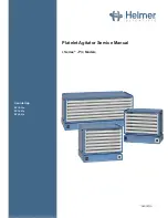
Helmer Scientific Platelet Agitator

Service Manual 

360391/A

7

2.4 

Placement Leveling and Setup (Stand-alone)

CAUTION

•  To prevent damage, do not use trolley or trolley drawer to lift agitator.
•  The communication switch is fragile, do not use excessive force when changing the setting.

NOTICE

•  When lifting platelet agitator, lift using the ends of the base.
•  If the base is not accessible, lift using the ends of the trolley

 Notes

•  Leveling feet may crack or wear over time. Check leveling feet periodically and replace as needed.
•  For setpoint of 72 CPM, rotate the arrow into the center of the green zone. This is the expanded 72 CPM setpoint area.
• 

For additional information regarding agitator setup, refer to the Platelet Agitator Pro Operation Manual.

1.  Place platelet agitator on sturdy surface.
2.  Adjust leveling feet to ensure platelet agitator is level.
3. 

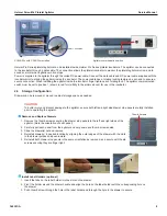
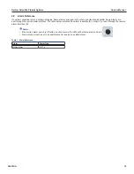
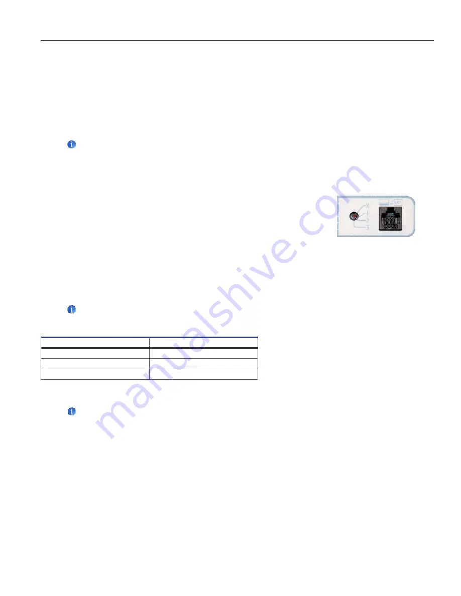
Using a small flathead screwdriver, turn the communication switch to the X position. 


  Ensure the arrow (shown in red for visibility in the picture) is pointing to the X.

2.5  Configure Platelet Agitator for Use in a Platelet Incubator (Optional) 

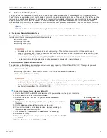
Pro Series platelet incubators may only be fitted with Pro Series platelet agitators. When installed in a Pro Series platelet incubator, 

the Pro Series platelet agitator can be monitored by the platelet incubator’s AgiTrak™ system. The AgiTrak™ system receives 
alarm information through a direct connection from the platelet agitator’s alarm system to the platelet incubator’s alarm system.

Platelet Agitator and Platelet Incubator Compatibility

 Note

Only Pro Series platelet incubators can monitor Pro Series platelet agitators.

Compatible Helmer Platelet Agitator

Platelet Incubator

PF15-Pro

PC100-Pro

PF48-Pro

PC900-Pro

PF96-Pro

PC1200-Pro

Install a Platelet Agitator in the Platelet Incubator

 Notes

• 

For additional instruction on configuring a platelet agitator in a platelet incubator, refer to the Platelet Incubator Pro


  Operation Manual.

•  Ensure data cable is carefully positioned to the right of the agitator to prevent damage caused by agitation motion.
•  The agitator communication switch is fragile, do not use excessive force when changing the setting. 
•  To ensure continuous operation of linearly shifting loads, the location surface must adequately accommodate the full  
  weight of the incubator with installed agitator when loaded with product. 
•  Use only the manufacturer supplied coiled DC power cord when installing the Pro series agitator in a Pro series Incubator.
•  Ensure the incubator AC power and battery back-up power are switched 

OFF

 prior to connecting the agitator power  

  cord to the incubator.
•  Installation of agitator anchor brackets is recommended when an installed agitator is set at a speed greater than  

  72 cycles per minute (CPM). Anchor brackets are included with the agitator.

•  The agitator motion alarm switch must be 

ON, 

and volume turned up to provide audible alarm backup in the event  

  communication is lost between the agitator and incubator. 

Summary of Contents for i.Series PF15-Pro

Page 1: ...360391 A Platelet Agitator Service Manual i Series Pro Models Countertop PF15 Pro PF48 Pro PF96 Pro...

Page 2: ...19 Helmer Inc All other trademarks and registered trademarks are the property of their respective owners Helmer Inc doing business as DBA Helmer Scientific and Helmer Disclaimer This manual is intende...

Page 3: ...ply 6 2 3 Mounting Brackets 6 2 4 Placement Leveling and Setup 7 2 5 Configure Platelet Agitator for Use in a Platelet Incubator Optional 7 2 6 Storage Configuration 8 2 7 External Monitoring Devices...

Page 4: ...nterference at his own expense Helmer platelet agitators are intended to provide controlled agitation required for the storage of platelet products The devices are intended to be operated by personnel...

Page 5: ...on Never physically restrict any moving component Avoid removing electrical service panels and access panels unless so instructed Keep hands away from pinch points when agitation motion is enabled Avo...

Page 6: ...Note Service information varies depending on the model and power requirements This information appears on the product specification label on the back of the platelet agitator C A B Sample Product Spec...

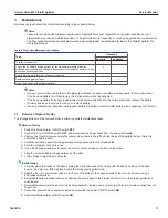
Page 7: ...r Supply 1 Remove the cover plate by using the thumb to push and hold the spring loaded locking key downward while sliding the plate forward Retain the cover plate in secure location for future use 2...

Page 8: ...irect connection from the platelet agitator s alarm system to the platelet incubator s alarm system Platelet Agitator and Platelet Incubator Compatibility Note Only Pro Series platelet incubators can...

Page 9: ...tion Drawers can be removed or moved to adjust storage space as needed CAUTION To avoid injury and prevent damage to the agitator ensure both left and right side drawer stop panels are fully installed...

Page 10: ...AC RMS or 70V DC is connected to the J2 remote alarm circuit the remote alarm will not function properly may be damaged or may result in injury to the user J3 Agitator Powered Remote Alarm Interface T...

Page 11: ...me Alarms are sent through the remote alarm interface The table below indicates if an alarm is audible A visual V or sent through the remote alarm interface R Notes If the motion alarm switch is ON wi...

Page 12: ...ry for replacement 9V NiMH battery with a capacity of 175 mAh 3 1 Remove Replace Trolley The storage trolley must be removed when performing certain maintenance tasks Remove Trolley 1 Switch the Motio...

Page 13: ...Alarm Volume is set to an audible level and the Alarm Delay is set to the minimum delay 2 Ensure the Motion Alarm ON OFF switch is ON 3 Switch the Power ON OFF switch OFF to stop agitation When the a...

Page 14: ...d turn on the power If operation is noisy or jerky replace the gearbox and motor Agitator is moving around on placement surface Placement surface is slick Relocate agitator to non slick surface Instal...

Page 15: ...C Drawer white 15 322731 1 069 J Motion Alarm Time Delay Switch 48 322749 1 069 K Agitator Communication Switch 96 322756 1 069 L Data Port for use with Pro Series Incubator Drawer stainless steel 15...

Page 16: ...ription Model Part Number A Wheel includes 4 wheels and brackets 801031 1 E Motor 15 48 801057 1 B Actuator Sensor 801035 1 96 801032 1 C 9V NiMH Rechargeable Back up Battery 120232 F Crank Block 8010...

Page 17: ...Helmer Scientific Platelet Agitator Service Manual 360391 A 16 Appendix A Wiring Diagram...

Page 18: ...ed at a location other than Helmer or for repairs made without the assistance of a Helmer technician will be the responsibility of the end user Additional Warranty Information The time periods set for...

Page 19: ...Helmer Scientific Platelet Agitator Service Manual 360391 A 18...

Page 20: ...Helmer Scientific 14400 Bergen Boulevard Noblesville IN 46060 USA Copyright 2019 Helmer Inc 360391 A...

Reviews: