Helmer Scientific Platelet Agitator
Service Manual
360391/A
9
2.7
External Monitoring Devices
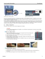
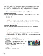
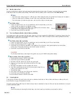
The agitator has two independent interfaces, each with spring loaded terminal pins for connecting external monitoring devices.
These interfaces are located directly on the agitator control board which is located in the base of the agitator (The trolley must be
removed to access these interfaces). One interface (J2) is a set of dry contacts with normally open or normally closed contacts
depending upon connector terminals used. The other interface (J3) set provides a switched 9-15V, 100mA powered output.
Requirements for your alarm system determine which alarm wires (user provided) must connect to specific connector terminals.
Note
When installed in a Pro series incubator, agitator alarms are communicated to the incubator.
J2 Dry Contact Remote Alarm Interface
The terminals on the J2 alarm interface have a maximum load capacity of 1 A at 33V (AC) RMS or 70V(DC). The dry contact
remote alarm interface is a relay switch with three terminals.
♦ Common (COM)
♦ Normally Open (NO)
♦ Normally Closed (NC)
CAUTION
•
Terminals on J2 are dry contacts and do not supply voltage. The interface circuit is NO or NC depending upon
connector terminals used. These connections are intended for use with an end user’s external alarm system(s) that
interface to NO or NC dry contacts.
•
If an external power supply exceeding 33V (AC) RMS or 70V (DC) is connected to the (J2) remote alarm circuit, the
remote alarm will not function properly; may be damaged; or may result in injury to the user.
J3 Agitator Powered Remote Alarm Interface
The terminals on the J3 alarm interface have a maximum supply capacity of 100 mA from 9-15V (DC). The agitator powered
remote alarm interface has three terminals.
♦ Reference 9-15V
♦ Normally Open (NO) << In an alarm condition, 9-15V will be connected to this terminal
♦ Circuit Ground Reference (GND)
CAUTION
• If any external power supply is connected to the J3 remote alarm circuit, the remote alarm or Agitator itself will not
function properly; may be damaged; or may result in injury to the user.
•
The Agitator does not limit the output current thru J3 – it is required that the end user’s central alarm system(s) interface
does not pull greater than 100 mA at 9-15V (DC).
Connect to Remote Alarm Interface (J2 or J3)
1.
Switch the ON/OFF switch
OFF
and disconnect the power cable from the power receptacle.
2.
Switch the motion alarm ON/OFF switch
OFF
.
3. Remove the trolley to access the agitator board in the base of
the agitator.
4. Route alarm wires into the agitator base through the rear access hole in
the base.
5.
On the alarm panel, locate the remote alarm terminals.
6. Connect remote alarm wires to appropriate terminals, according to
requirements for your alarm system.
7.
Use a cable tie to relieve strain on alarm wires (as necessary).
8. Reinstall the trolley.
9.
Reconnect the power cable to power receptacle, and switch the ON/OFF
switch
ON
.
10.
Switch the motion alarm ON/OFF switch
ON
.
Remote alarm interfaces.

