22
Chapter 2: Installation
Connecting the V102 to External Devices
Power/Data Cable Considerations
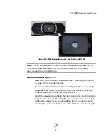
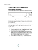
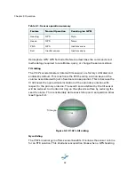
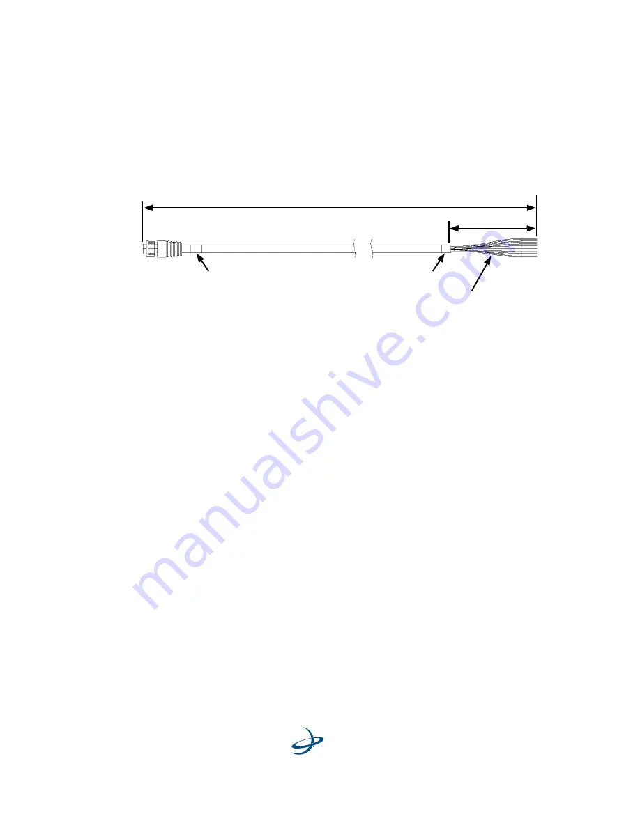
The V102 uses a single 15 m (49 ft) cable for power and data input/output.
Figure 2-8: Power/data cable, 15 m
The receiver end of the cable is terminated with an environmentally sealed
12-pin connection while the opposite end is unterminated and requires field
stripping and tinning.
Depending on the application and installation needs, you may need to
shorten this cable. However, if you require a longer cable run than 15 m, you
can bring the cable into a break-out box that incorporates terminal strips,
within the vessel.
When lengthening the cable keep the following in mind:
•
To lengthen the serial lines inside the vessel, use 20-gauge twisted
pairs and minimize the additional wire length.
•
When lengthening the power input leads to the V102, ensure the
additional voltage drop is small enough that your power system can
continue to power the system above the minimum voltage of the
system. Wire of 18-gauge or larger should also be used.
•
Minimize RS-232 cable length to ensure reliable communication
J1
P1
30 mm
Strip and tin 3 mm
25 mm
100 mm
15 m
Summary of Contents for V102 G
Page 1: ...V102 GPS Compass User Guide Part No 875 0276 000 Rev C1 ...
Page 6: ...Chapter 1 Introduction Overview Parts List ...
Page 9: ......
Page 32: ...Chapter 3 Operation GPS Overview V102 Overview Common Commands and Messages ...
Page 46: ...Appendix A Troubleshooting ...
Page 50: ...Appendix B Specifications ...
Page 60: ...www hemispheregps com ...


