V102 GPS Compass User Guide
23
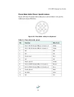
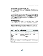
Power/Data Cable Pinout Specifications
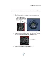
Figure 2-9 show the power/data cable pinout, while Table 2-1 shows the
cable’s pinout specifications.
Figure 2-9: Power/data cable pin assignment
Table 2-1: Power/data cable pinout
Pin
Function
Wire Color
1
Port C, RS-232 female DB9 pin 2, device out
White
2
Port C, RS-232 female DB9 pin 3, device in
Green
3
N/C
N/C
4
N/C
N/C
5
Power input
Red
6
N/C
N/C
7
Signal ground
Yellow
8
Port A, RS-232 female DB9 pin 3, device in
Brown
9
Port A, RS-232 female DB9 pin 2, device out
Blue
10
Power ground
Black
11
CH_GND
Drain
12
N/C
N/C
Summary of Contents for V102 G
Page 1: ...V102 GPS Compass User Guide Part No 875 0276 000 Rev C1 ...
Page 6: ...Chapter 1 Introduction Overview Parts List ...
Page 9: ......
Page 32: ...Chapter 3 Operation GPS Overview V102 Overview Common Commands and Messages ...
Page 46: ...Appendix A Troubleshooting ...
Page 50: ...Appendix B Specifications ...
Page 60: ...www hemispheregps com ...


