background image

estimate of achievable accuracy based on specifications provided by the US Department of Defense for GPS positioning and DGPS 
service provider performance specifications, where applicable.

10.

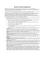
WARRANTY DISCLAIMER.

 EXCEPT AS EXPRESSLY SET OUT IN THIS AGREEMENT, HEMISPHERE MAKES NO REPRESENTATION, 

WARRANTY OR CONDITION OF ANY KIND TO LICENSEE, WHETHER VERBAL OR WRITTEN AND HEREBY DISCLAIMS ALL 
REPRESENTATIONS, WARRANTIES AND CONDITIONS OF ANY KIND INCLUDING FITNESS FOR A PARTICULAR PURPOSE, 
MERCHANTABILITY, ACCURACY, RELIABILITY OR THAT THE USE OF THE SOFTWARE WILL BE UNINTERRUPTED OR ERROR-FREE 
AND HEREBY DISCLAIMS ALL REPRESENTATIONS, WARRANTIES AND CONDITIONS ARISING AS A RESULT OF CUSTOM, USAGE 
OR TRADE AND THOSE ARISING UNDER STATUTE.

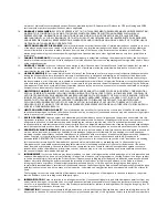
11.

LIMITS ON WARRANTY DISCLAIMER.

 Some jurisdictions do not allow the exclusion of implied warranties or conditions, so some 

of the above exclusions may not apply to Licensee. In that case, any implied warranties or conditions which would then otherwise 
arise will be limited in duration to ninety (90) days from the date of the license of the Software or the purchase of the Product. The 
warranties given herein give Licensee specific legal rights and Licensee may have other rights which may vary from jurisdiction to 
jurisdiction.

12.

CHANGE TO WARRANTY.

 No employee or agent of Hemisphere is authorized to change the warranty provided or the limitation or 

disclaimer of warranty provisions. All such changes will only be effective if pursuant to a separate agreement signed by senior officers 
of the respective parties.

13.

WARRANTY CLAIM.

 In the event Licensee has a warranty claim Licensee must first check for and install all Updates that are made 

available. The warranty will not otherwise be honored. Proof of purchase may be required. Hemisphere does not honor claims 
asserted after the end of the Warranty Period.

14.

LICENSEE REMEDIES. 

In all cases which involve a failure of the Software to conform in any material respect to the documentation 

during the Warranty Period or a breach of a warranty, Hemisphere's sole obligation and liability, and Licensee's sole and exclusive 
remedy, is for Hemisphere, at Hemisphere's option, to (a) repair the Software, (b) replace the Software with software conforming to 
the documentation, or (c) if Hemisphere is unable, on a reasonable commercial basis, to repair the Software or to replace the Software 
with conforming software within ninety (90) days, to terminate this Agreement and thereafter Licensee shall cease using the Software. 
Hemisphere will also issue a refund for the price paid by Licensee less an amount on account of amortization, calculated on a straight-
line basis over a deemed useful life of three (3) years.

15.

LIMITATION OF LIABILITY

. IN NO EVENT WILL HEMISPHERE BE LIABLE TO LICENSEE FOR ANY INCIDENTAL, CONSEQUENTIAL, 

SPECIAL OR INDIRECT DAMAGES INCLUDING ARISING IN RELATION TO ANY LOSS OF DATA, INCOME, REVENUE, GOODWILL OR 
ANTICIPATED SAVINGS EVEN IF HEMISPHERE HAS BEEN INFORMED OF THE POSSIBILITY OF SUCH LOSS OR DAMAGE. FURTHER, 
IN NO EVENT WILL HEMISPHERE'S TOTAL CUMULATIVE LIABILITY HEREUNDER, FROM ALL CAUSES OF ACTION OF ANY KIND, 
EXCEED THE TOTAL AMOUNT PAID BY LICENSEE TO HEMISPHERE TO PURCHASE THE PRODUCT. THIS LIMITATION AND 
EXCLUSION APPLIES IRRESPECTIVE OF THE CAUSE OF ACTION, INCLUDING BUT NOT LIMITED TO BREACH OF CONTRACT, 
NEGLIGENCE, STRICT LIABILITY, TORT, BREACH OF WARRANTY, MISREPRESENTATION OR ANY OTHER LEGAL THEORY AND WILL 
SURVIVE A FUNDAMENTAL BREACH.

16.

LIMITS ON LIMITATION OF LIABILITY.

 Some jurisdictions do not allow for the limitation or exclusion of liability for incidental or 

consequential damages, so the above limitation or exclusion may not apply to Licensee and Licensee may also have other legal rights 
which may vary from jurisdiction to jurisdiction.

17.

BASIS OF BARGAIN. 

Licensee agrees and acknowledges that Hemisphere has set its prices and the parties have entered into this 

Agreement in reliance on the limited warranties, warranty disclaimers and limitations of liability set forth herein, that the same reflect 
an agreed-to allocation of risk between the parties (including the risk that a remedy may fail of its essential purpose and cause 
consequential loss), and that the same forms an essential basis of the bargain between the parties. Licensee agrees and acknowledges 
that Hemisphere would not have been able to sell the Product at the amount charged on an economic basis without such limitations.

18.

PROPRIETARY RIGHTS INDEMNITY

. Hemisphere shall indemnify, defend and hold harmless Licensee from and against any and all 

actions, claims, demands, proceedings, liabilities, direct damages, judgments, settlements, fines, penalties, costs and expenses, 
including royalties and attorneys' fees and related costs, in connection with or arising out of any actual infringement of any third party 
patent, copyright or other intellectual property right by the Software or by its use, in accordance with this Agreement and 
documentation, PROVIDED THAT: (a) Hemisphere has the right to assume full control over any action, claim, demand or proceeding, 
(b) Licensee shall promptly notify Hemisphere of any such action, claim, demand, or proceeding, and (c) Licensee shall give 
Hemisphere such reasonable assistance and tangible material as is reasonably available to Licensee for the defense of the action, 
claim, demand or proceeding. Licensee shall not settle or compromise any of same for which Hemisphere has agreed to assume 
responsibility without Hemisphere's prior written consent. Licensee may, at its sole cost and expense, retain separate counsel from 
the counsel utilized or retained by Hemisphere.

19.

INFRINGEMENT.

 If use of the Software may be enjoined due to a claim of infringement by a third party then, at its sole discretion and 

expense, Hemisphere may do one of the following: (a) negotiate a license or other agreement so that the Product is no longer subject 
to such a potential claim, (b) modify the Product so that it becomes non-infringing, provided such modification can be accomplished 
without materially affecting the performance and functionality of the Product, (c) replace the Software, or the Product, with non-
infringing software, or product, of equal or better performance and quality, or (d) if none of the foregoing can be done on a 
commercially reasonable basis, terminate this license and Licensee shall stop using the Product and Hemisphere shall refund the price 
paid by Licensee less an amount on account of amortization, calculated on a straight-line basis over a deemed useful life of three (3) 
years.

The foregoing sets out the entire liability of Hemisphere and the sole obligations of Hemisphere to Licensee in respect of any claim 
that the Software or its use infringes any third party rights.

20.

INDEMNIFICATION

. Except in relation to an infringement action, Licensee shall indemnify and hold Hemisphere harmless from any 

and all claims, damages, losses, liabilities, costs and expenses (including reasonable fees of lawyers and other professionals) arising 
out of or in connection with Licensee's use of the Product, whether direct or indirect, including without limiting the foregoing, loss of 
data, loss of profit or business interruption.

21.

TERMINATION

. Licensee may terminate this Agreement at any time without cause. Hemisphere may terminate this Agreement on 30 

days notice to Licensee if Licensee fails to materially comply with each provision of this Agreement unless such default is cured within 

Summary of Contents for V102 G

Page 1: ...V102 GPS Compass User Guide Part No 875 0276 000 Rev C1 ...

Page 2: ...M IntelliTracTM Just Let GoTM L DifTM LiteStar IITM LV101TM LX 1TM LX 2TM M3TM MapStar MBX 4TM miniEclipseTM OutbackTM Outback 360TM Outback Guidance CenterTM Outback Guidance Outback HitchTM Outback STM Outback S2TM Outback S3TM Outback S LiteTM Outback StsTM Outback Steering GuideTM PocketMAX PCTM PocketMAXTM PocketMax3TM R100TM R131TM R220TM R320TM Satloc the Satloc logo SBX 4TM V101TM V102TM V...

Page 3: ...m Technical Support If you need to contact Hemisphere GPS Technical Support 8444 N 90th St Suite 130 Scottsdale AZ 85258 USA Phone 480 348 9919 Fax 480 348 6370 techsupport hemispheregps com Documentation Feedback Hemisphere GPS is committed to the quality and continuous improvement of our products and services We urge you to provide Hemisphere GPS with any feedback regarding this guide by writing...

Page 4: ... VHF Interference 7 Mounting Orientation 9 V102 Alignment 11 Mounting Options 12 V102 Dimensions 13 Power Data Cable Considerations 14 Flush Mount 14 Pole Mount 18 Powering the V102 21 Power Considerations 21 Connecting to a Power Source 21 Electrical Isolation 21 Connecting the V102 to External Devices 22 Power Data Cable Considerations 22 Power Data Cable Pinout Specifications 23 ...

Page 5: ...ation 28 Differential Operation 29 V102 Overview 30 Fixed Baseline Moving Base Station RTK 30 Supplemental Sensors 31 Time Constants 34 Watchdog 35 Common Commands and Messages 36 Appendix A Troubleshooting 41 Appendix B Specifications 45 Index 49 End User License Agreement 51 Warranty Notice 54 ...

Page 6: ...Chapter 1 Introduction Overview Parts List ...

Page 7: ...n the event that a GPS heading is not available due to signal blockage Crescent Vector II technology supports multiple RF front ends enabling tighter coupling of measurements from separate antennas for use in heading based products Users will achieve excellent accuracy and stability due to Crescent s more accurate code phase measurements improved multipath mitigation and fewer components The V102 ...

Page 8: ...from the Hemisphere GPS website at www hemispheregps com Parts List Note The V102 s parts comply with IEC 60945 Section 4 4 exposed to the weather The V102 GPS Compass and the power data cable accessory item are the only two required components This User Guide is available for download from the Hemisphere GPS website at www hemispheregps com Table 1 1 Parts list Part Name Qty Part Number V102 GPS ...

Page 9: ......

Page 10: ...Chapter 2 Installation Mounting Location Mounting Orientation Mounting Options Powering the V102 Connecting the V102 to External Devices ...

Page 11: ...ce Since the V102 computes a position based on the internal primary GPS antenna element mount the V102 where you desire a position with respect to the primary GPS antenna located on the end opposite the recessed arrow on the underside of the enclosure Locate any transmitting antennas away from the V102 by at least several feet to ensure tracking performance is not compromised giving you the best p...

Page 12: ...F marine radio working frequencies Channels 1 to 28 and 84 to 88 range from 156 05 to 157 40 MHz The L1 GPS working center frequency is 1575 42 MHz The bandwidth is 2MHz to 10 MHz which is dependent on the GPS antenna and receiver design VHF marine radios emit strong harmonics The 10th harmonic of VHF radio in some channels falls into the GPS working frequency band which may cause the SNR of GPS t...

Page 13: ...owing diagram to ensure there are no nearby devices that may cause VHF interference Figure 2 1 V102 distance from nearby VHF radios 1 5 m radius at top minimum 1 0 m radius at base minimum Use these minimum distances to determine where to place the V102 VHF Antenna ...

Page 14: ...lel to and along the centerline of the axis of the boat This provides a true heading In this orientation If you use a gyrocompass you can enter a heading bias in the V102 to calibrate the physical heading to the true heading of the vessel You may need to adjust the pitch roll output to calibrate the measurement if the Vector is not installed in a horizontal plane Perpendicular Orientation You can ...

Page 15: ...ntation examples Figure 2 2 Recommended orientation and resulting signs of HPR values Figure 2 3 Alternate orientation and resulting signs of HPR values Forward motion Recessed arrow located on bottom of enclosure Forward motion Recessed arrow located on bottom of enclosure ...

Page 16: ...and Figure 2 5 Alignment accuracy when looking through the long site Figure 2 4 is approximately 1 while alignment through the short site Figure 2 5 is approximately 2 5 Figure 2 4 Long site alignment Figure 2 5 Short sight alignment If you have another accurate source of heading data on your vessel such as a gyrocompass you may use its data to correct for a bias in V102 alignment within the V102 ...

Page 17: ...les for flush mounting the unit to a flat surface see Figure 2 6 on page 13 Pole mount The bottom of the V102 contains a mounting hole 1 thread 0 9 depth for easy pole mounting Hand tighten until snug do not overtighten The set screws on the long sides of the base see middle drawing in Figure 2 6 on page 13 allow you to secure the V102 in place 3 16 Allen wrench not included ...

Page 18: ...trates the physical dimensions of the V102 Figure 2 6 V102 dimensions C L C L 68 90 mm 2 71 SET SCREW 3 8 16 THREAD SIZE 2 PLACES MOUNTING HOLE 1 14 UNS 2A THREAD SIZE MOUNTING HOLE M8 THREAD SIZE 4 PLACES 414 39 mm 16 31 157 89 mm 6 21 46 99 mm 31 75 mm 1 25 1 85 ...

Page 19: ...mp or excessively bend the cable Avoid placing tension on the cable Remove unwanted slack from the cable at the V102 end Secure along the cable route using plastic wraps Improperly installed cable near machinery can be dangerous Flush Mount The bottom of the V102 contains four holes for flush mounting the unit to a flat surface Figure 2 7 The flat surface may be something you fabricate per your in...

Page 20: ...ng orientation See Mounting Orientation on page 9 for more information Choose a location that meets the mounting location requirements Using the fixed base as a template mark and drill the mounting holes as necessary for the mounting surface Attach the power data cable to the cable clamp and attach the clamp to the bottom of the V102 using the screw and washer Do not fully tighten the screw so you...

Page 21: ...ng hole centers on the mounting surface 3 Place the V102 over the marks to ensure the planned hole centers align with the true hole centers adjusting as necessary 4 Use a center punch to mark the hole centers 5 Drill the mounting holes with a 9 mm bit appropriate for the surface 6 Place the V102 over the mounting holes and insert the mounting screws through the bottom of the mounting surface and i...

Page 22: ...onnector keyway with the V102 connector key 2 Rotate the cable ring clockwise until it locks The locking action is firm but you will feel a positive click when it has locked 3 Tighten the clamp securing the cable to the V102 Make sure the connector keyway on the cable matches up with the connector key on the V102 Cable connector keyway V102 connector key Cable ring ...

Page 23: ...ing the V102 Decide if you need the roll measurement If you need roll measurement the V102 will need to be installed perpendicular to the vessel axis If it you do not need roll measurement install the V102 parallel with the vessel s axis Choose a location that meets the mounting location requirements Mark and drill the mounting holes as necessary for the threaded pole Attach the power data cable t...

Page 24: ...e on page 20 Routing the cable Run the cable through the pole and then through any bulkheads as needed Leave some slack to move the cable in and out of the pole mount by a few inches centimeters to allow you to connect the cable to the V102 easily ...

Page 25: ... locks The locking action is firm but you will feel a positive click when it has locked 3 Tighten the clamp securing the cable to the V102 Note See V102 Dimensions on page 13 for information on routing the power data cable Make sure the connector keyway on the cable matches up with the connector key on the V102 Cable connector keyway V102 connector key Cable ring ...

Page 26: ...the market from which to choose depending on your specific requirements Do not apply a voltage higher than 36 VDC This will damage the receiver and void the warranty To interface the V102 power cable to the power source Connect the red wire of the cable s power input to DC positive Connect the black wire of the cable s power input to DC negative The V102 will start when an acceptable voltage is ap...

Page 27: ...ver if you require a longer cable run than 15 m you can bring the cable into a break out box that incorporates terminal strips within the vessel When lengthening the cable keep the following in mind To lengthen the serial lines inside the vessel use 20 gauge twisted pairs and minimize the additional wire length When lengthening the power input leads to the V102 ensure the additional voltage drop i...

Page 28: ...able pin assignment Table 2 1 Power data cable pinout Pin Function Wire Color 1 Port C RS 232 female DB9 pin 2 device out White 2 Port C RS 232 female DB9 pin 3 device in Green 3 N C N C 4 N C N C 5 Power input Red 6 N C N C 7 Signal ground Yellow 8 Port A RS 232 female DB9 pin 3 device in Brown 9 Port A RS 232 female DB9 pin 2 device out Blue 10 Power ground Black 11 CH_GND Drain 12 N C N C ...

Page 29: ... Port A or Port C of the GPS receiver to output any combination of data that you want Port A can have a different configuration from Port C in terms of data message output data rates and the baud rate of the port This allows you to configure the ports independently based upon your needs For example if you want one generalized port and one heading only port you can configure the ports as follows Po...

Page 30: ...ess the other device has a terminal setting where you can manually issue commands Default Parameters Table 2 2 and Table 2 3 provide details on the default port settings available baud rates differential age elevation mask and default differential mode Note Use the JSAVE command to save changes you make to the V102 s configuration for the changes to be present in subsequent power cycles Table 2 2 ...

Page 31: ...26 Chapter 2 Installation Table 2 3 Additional default settings Parameter Specification Max DGPS age correction age 2700 seconds Elevation mask 5 Differential mode SBAS WAAS EGNOS ...

Page 32: ...Chapter 3 Operation GPS Overview V102 Overview Common Commands and Messages ...

Page 33: ...describe the general operation of the V102 s internal GPS receiver Note Differential source and status have no impact on heading pitch or roll They only have an impact on positioning and heave Automatic Tracking The V102 s internal GPS receiver automatically searches for GPS satellites acquires the signals and manages the navigation information required for positioning and tracking Receiver Perfor...

Page 34: ...ential GPS DGPS is to remove the effects of selective availability SA atmospheric errors timing errors and satellite orbit errors while enhancing system integrity Autonomous positioning capabilities of the V102 will result in positioning accuracies of 2 5 m 95 of the time In order to improve positioning quality to better than 1 0 m 95 the V102 is able to use differential corrections received throu...

Page 35: ...h the L1 GPS C A code and carrier phase data to compute the location of the secondary GPS antenna in relation to the primary GPS antenna with a very high sub centimeter level of precision The technique of computing the location of the secondary GPS antenna with respect to the primary antenna when the primary antenna is moving is often referred to as moving base station Real Time Kinematic or movin...

Page 36: ... The gyro and tilt sensors are enabled by default Each supplemental sensor may be individually enabled or disabled Both supplemental sensors are mounted on the printed circuit board inside the V102 The sensors act to reduce the RTK search volume which improves heading startup and reacquisition times This improves the reliability and accuracy of selecting the correct heading solution by eliminating...

Page 37: ... secondary antenna with respect to the primary antenna The search space defined by the tilt sensor will be reduced to a horizontal ring on the sphere s surface by reducing the search volume This considerably decreases startup and reacquisition times see Figure 3 2 Figure 3 2 V102 s tilt aiding Gyro Aiding The V102 s internal gyro offers several benefits It reduces the sensor volume for an RTK solu...

Page 38: ...o far and the V102 begins outputting null fields in the heading output messages There is no user control over the timeout period of the gyro Calibration which is set at the factory is required for the gyro to remove latency from the heading solution as well as provide backup heading when GPS is blocked The receiver will calibrate itself after running for a while but it may be important to follow t...

Page 39: ...lues would have reduced noise resulting in consistent values with time However if the vessel is quick and nimble increasing this value can create a lag in measurements Formulas for determining the level of smoothing are located in Hemisphere GPS GPS Technical Reference If you are unsure on how to set this value it is best to be conservative and leave it at the default setting Note For heading and ...

Page 40: ...ue of this constant is 0 0 seconds of smoothing Increasing the time constant increases the level of COG smoothing COG is computed using only the primary GPS antenna and its accuracy depends upon the speed of the vessel noise is proportional to 1 speed This value is invalid when the vessel is stationary as tiny movements due to calculation inaccuracies are not representative of a vessel s movement ...

Page 41: ...ssages for the V102 Refer to the Hemisphere GPS Technical Reference for more detailed information Table 3 2 Commands Command Description JAGE Specify maximum DGPS COAST correction age 6 to 8100 seconds JAPP Query or specify receiver application firmware JASC Specify ASCII messages to output to specific ports see ASCII messages in Table 3 3 JBAUD Specify RS 232 RS 422 output communication rate JBIN...

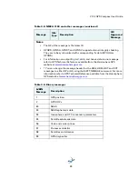
Page 42: ... receiver has reset Failure to do so will cause radical heading behavior JSAVE Save session s configuration changes Table 3 3 NMEA 0183 and other messages Message Info Type Description IEC Approved Message GPDTM P Datum reference Yes GPGGA P GPS position and fix data Yes GPGLL P Geographic position lat long Yes GPGNS P GNSS position and fix data Yes GPGRS S GNSS range residual RAIM Yes GPGSA S GNS...

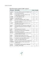
Page 43: ...t in Note at end of this table Yes GPRRE S Range residual and estimated position error Yes GPVTG V COG and ground speed Yes GPZDA V Time and date Yes PASHR H Time heading roll and pitch data in one message No PSAT GBS S Satellite fault detection RAIM Yes PSAT HPR H Proprietary NMEA message that provides heading pitch roll and time in single message No PSAT INTLT H Proprietary NMEA message that pro...

Page 44: ...he message header for the HDG HDM HDT and ROT messages to either GP or HE using the JATT NMEAHE command For more information refer to GPS Technical Reference available from the Hemisphere GPS website at www hemispheregps com Table 3 4 Binary messages JBIN Message Description 1 GPS position 2 GPS DOPs 80 SBAS 93 SBAS ephemeris data 94 Ionosphere and UTC conversion parameters 95 Satellite ephemeris ...

Page 45: ...ts X X HRTAU Set query ROT time constant 0 0 to 3600 0 sec X X HTAU Set query heading time constant 0 0 to 3600 0 sec X X LEVEL Enable disable level operation X X MSEP Manually set or query antenna separation X X NEGTILT Enable disable negative tilt X X NMEAHE Change the HDG HDM HDT and ROT message headers between GP and HE X X PBIAS Set query pitch roll bias 15 0º to 15 0º X X PTAU Set query pitc...

Page 46: ...Appendix A Troubleshooting ...

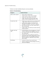
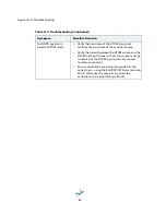
Page 47: ...d using PocketMax or JSHOW in any terminal program Ensure the baud rate of the V102 matches that of the receiving device Check integrity and connectivity of power and data cable connections Random data from V102 Verify the RTCM or binary messages are not being output accidentally send a JSHOW command Ensure the baud rate of the V102 matches that of the remote device Potentially the volume of data ...

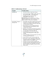
Page 48: ...AL command if heading is calculated then lost at consistent time intervals Heading is from primary GPS antenna to secondary GPS antenna so the arrow on the underside of the V102 should be directed to the bow side JATT SEARCH command forces the V102 to acquire a new heading solution unless gyro is enabled Enable GYROAID to provide heading for up to three minutes during GPS signal loss Enable TILTAI...

Page 49: ...ween the RTCM source and the RTCM input port transmit from the source must go to receive of the RTCM input port and grounds must be connected Ensure corrections are being transmitted to the correct port using the JDIFF PORTB command on Port A will cause the receiver to expect the corrections to be input through Port B Table A 1 Troubleshooting continued Symptom Possible Solution ...

Page 50: ...Appendix B Specifications ...

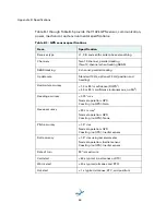
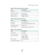
Page 51: ... 10 Hz optional 20 Hz position and heading Horizontal accuracy 1 0 m 95 confidence DGPS1 2 5 m 95 confidence autonomous no SA2 Heading accuracy 0 75 rms Normal operation GPS Coasting no GPS Gyro Heave accuracy 30 cm rms5 Normal operation GPS Coasting no GPS None Pitch accuracy 1 5 rms Normal operation GPS Coasting no GPS Inertial sensor Roll accuracy 1 5 rms using accelerometer Normal operation In...

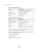
Page 52: ...full duplex RS 232 Baud rates 4800 9600 19200 38400 57600 115200 Correction I O protocol RTCM SC 104 Data I O protocol NMEA 0183 Crescent binary3 CAN Table B 3 Power specifications Item Specification Input voltage 6 to 36 VDC Power consumption 3 W nominal Current consumption 320 mA 9 VDC 240 mA 12 VDC 180 mA 16 VDC Power isolation Isolated to enclosure Reverse polarity protection Yes Table B 1 GPS...

Page 53: ...a 40 second time constant Table B 4 Mechanical specifications Item Specification Enclosure UV resistant white plastic AES HW 600G non corrosive self extinguishing Dimensions not including mounts 41 7 L x 15 8 W x 6 9 H cm 16 4 L x 6 2 W x 2 7 H in Weight 1 50 kg 3 3 lb Table B 5 Environmental specifications Item Specification Operating temperature 30 C to 70 C 22 F to 158 F Storage temperature 40 ...

Page 54: ...l considerations 7 external devices 22 F fixed base station RTK 30 flush mount 14 G GPHEV 9 38 GPS automatic SBAS tracking 29 automatic tracking 28 operation 28 overview 28 receiver performance 28 reception 6 sensor specifications 46 gyro aiding 32 H heading time constant 34 heave 9 38 accuracy 46 HRTAU 35 40 HTAU 34 40 L long sight alignment 11 M mechanical specifications 48 message common 36 mou...

Page 55: ...40 R rate of turn ROT time constant 35 receiver performance 28 RS 232 22 23 24 25 36 47 S sensor specifications 46 short site alignment 11 SPDTAU 35 40 specifications communication 47 environmental 48 GPS sensor 46 mechanical 48 power 47 speed time constant 35 supplemental sensors 31 T tilt aiding 32 time constants 34 COGTAU 35 HRTAU 35 HTAU 34 PTAU 34 SPDTAU 35 tracking automatic 28 automatic SBA...

Page 56: ... without any obligation to notify supply or install any improvements or alterations to existing Software 4 SUPPORT Hemisphere may make available directly or through its authorized dealers telephone and email support for the Software Contact Hemisphere to find the authorized dealer near you As well Hemisphere may make available user and technical documentation regarding the Software Hemisphere rese...

Page 57: ...damages so the above limitation or exclusion may not apply to Licensee and Licensee may also have other legal rights which may vary from jurisdiction to jurisdiction 17 BASIS OF BARGAIN Licensee agrees and acknowledges that Hemisphere has set its prices and the parties have entered into this Agreement in reliance on the limited warranties warranty disclaimers and limitations of liability set forth...

Page 58: ...ts war riot insurrection epidemic Internet virus attack Internet failure supplier failure act of God or governmental action not the fault of the non performing party 25 FORUM FOR DISPUTES The parties agree that the courts located in Calgary Alberta Canada and the courts of appeal there from will have exclusive jurisdiction to resolve any disputes between Licensee and Hemisphere concerning this Agr...

Page 59: ...ce or accuracy of any Product HEMISPHERE IS NOT RESPONSIBLE FOR PURCHASER S NEGLIGENCE OR UNAUTHORIZED USES OF THE PRODUCT IN NO EVENT SHALL HEMISPHERE GPS BE IN ANY WAY RESPONSIBLE FOR ANY DAMAGES RESULTING FROM PURCHASER S OWN NEGLIGENCE OR FROM OPERATION OF THE PRODUCT IN ANY WAY OTHER THAN AS SPECIFIED IN HEMISPHERE GPS S RELEVANT USER S MANUAL AND SPECIFICATIONS Hemisphere GPS is NOT RESPONSI...

Page 60: ...www hemispheregps com ...

Reviews: