5
EN
Preparation for installation
After unpacking of the device, a power supply, a
2.5” wrench for the head flange, 3/4” seals and 3/4”
connectors shall be taken out of the brine tank.
Only the special recesses in the housing shall be
used to lift and move the device around. The device
shall not be lifted by its electric cables or water
hoses due to damage that might occur.
Before installing, ensure that water mains pres-
sure is above 1.5 bar and below 6.0 bar. Shall the
pressure be higher, a reducing valve shall be in-
stalled upstream the device.
A location as close as possible to the water inlet of
a building shall be chosen (a water meter in case
of mains water supply or a hydrophore in case of
own water source/inlet) and in the vicinity of drain-
age. Moreover, permanent electric power supply is
necessary, therefore a socket must be near. The
surface of installation must be stable and must
withstand the weight of the device filled with water.
Ambient temperature in the selected installation
area shall never drop below 5°C, otherwise the
device may be permanently damaged. The devices
shall not be installed in rooms with excessive air
humidity. What is more, the selected area shall be
large enough to guarantee free access to the de-
vice, as it requires periodical refilling of salt.
Installation
The connectors of the control head are marked as
IN (inlet) and OUT (outlet), looking from the front of
the control head: IN (inlet) on the right, OUT (out-
let) on the left. The seals and connectors provided
shall be placed/fixed onto the connectors of the
control head. The water softener shall be connect-
ed to the system with flexible hoses (not provided).
A mechanical filter shall be installed upstream the
softener, of at least 50 microns, in order to protect
the device against impurities.
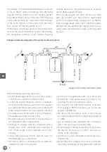
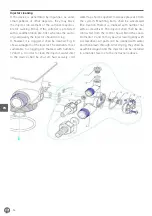
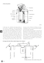
A by-pass can be executed by means of regular
valves, as indicated in Fig. A. A turbine must be in-
stalled in a nipple fixed onto the “OUT” connector
of the control head. Before installation, make sure
that the turbine rotates freely (e.g., by blowing air
into the water outlet). The device shall be installed
by means of materials intended for water installa-
tions. In case of any problems or doubts, contact
a qualified installation company or an authorized
service company.
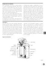
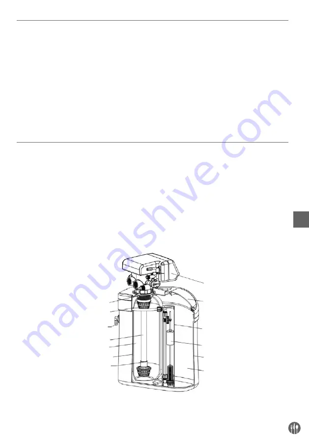
Diagram of the device
Control head
Cover
Flange
Upper basket
Overflow elbow
Distrubution pipe
Resin
Lower basket
Brine valve pit
Brine valve
Cabinet
Salt
Container
Fig. A


