background image

EN

16

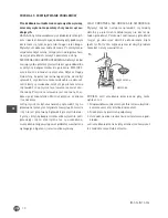
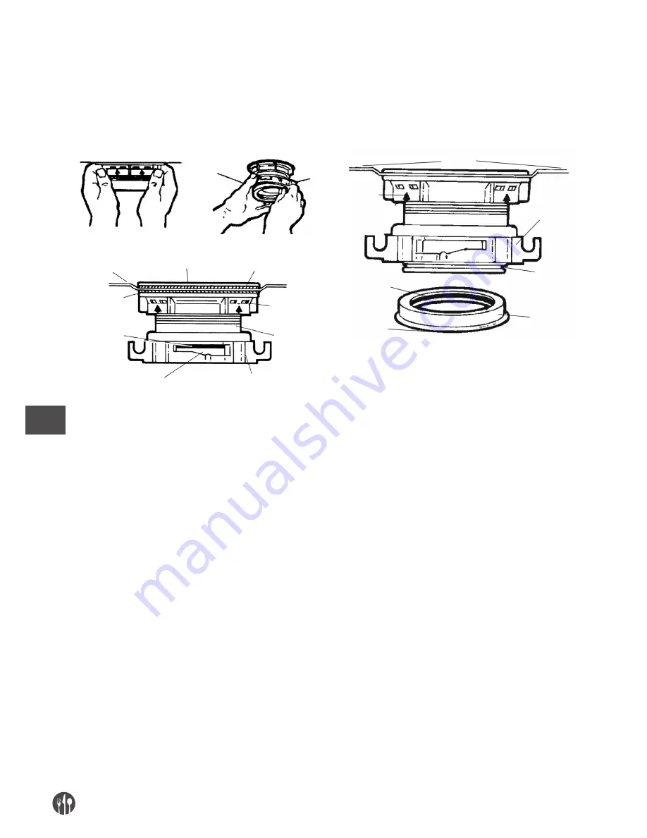
IMPORTANT NOTICE:  CUSHION MOUNT 

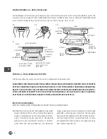
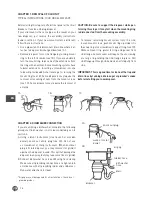
When the cushion mount is installed correctly, the lip of the sink flange fits into the groove on the inside of the cushion

mount and mount ring can be pulled downward over cushion mount and will be free to rotate. The bottom bead of

the cushion mount acts as a gasket between the bottom of the sink flange and the top of the disposer. See illustration 3G.

CHAPTER 4. ELECTRICAL CONNECTIONS

A. Connect disposer to appropriate household current only.

DANGER: IMPROPER CONNECTION OF THE EQUIPMENT-GROUNDING CONDUCTOR CAN RESULT IN 

A RISK OF ELECTRIC SHOCK. CHECK WITH A QUALIFIED ELECTRICIAN OR SERVICEMAN IF YOU ARE IN

DOUBT AS TO WHETHER THE APPLIANCE IS PROPERLY GROUNDED. DO NOT MODIFY THE PLUG 

PROVIDED WITH THE APPLIANCE IF IT WILL NOT FIT THE OUTLET. HAVE A PROPER OUTLET INSTALLED

BY A QUALIFIED ELECTRICIAN.

support

ring

groove

bottom

bead

cushion
mount

mount
ring

bottom

“lip“ of sink

flange

3E

3D

3G

sink

fiber

top of sink flange

rubber gasket

open area,
no obstruction

mount ring should be
free to move up & down

ring sink
flange

support

bottom 

bead of

cushion

mount

B. This appliance must be grounded. In the event of 

a malfunction or breakdown, grounding provides a path

of least resistance for electric current to reduce the

risk of electric shock. This appliance is equipped

with a cord having an equipment-grounding con-

ductor and a grounding plug. The plug must be

plugged into an appropriate outlet that is properly

installed and grounded in accordance with all local

codes and ordinances. If the supply cord is damaged

it must be replaced by the manufacturer, its service

agent or similarly qualified person in order to avoid

a hazard.

GROUNDING INSTRUCTIONS

FOR WASTE DISPOSERS EQUIPPED WITH A GROUNDED PLUG-IN POWER CORD.

Summary of Contents for 975084

Page 1: ...obs ugi You should read these user instructions carefully before using the appliance Przed uruchomieniem urz dzenia nale y koniecznie dok adnie przeczyta niniejsz instrukcj obs ugi 975084 M YNEK DO O...

Page 2: ...U YTEGO URZ DZENIA 4 ROZDZIA 2 POD CZENIE ZMYWARKI 4 ROZDZIA 3 INSTALACJA ZESPO U MOCUJ CEGO 5 ROZDZIA 4 PO CZENIA ELEKTRYCZNE 6 ROZDZIA 5 MONTA KOLANKA SPUSTOWEGO 7 ROZDZIA 6 POD CZANIE M YNKA DO ZES...

Page 3: ...m zaci cia lub przedmiotu z m ynka nale y wy czy urz dzenie po o enie wy off Do usuni cia zaci cia nale y u y d ugiego drewnianego przedmiotu np drewnianej y ki albo kija od miot y czy mopa Do usuwani...

Page 4: ...mocuj cego Aby zdj pozosta e elementy mocuj ce ze zlewu na le y poluzowa ruby mocuj ce i wypchn pier cie mocuj cy w g r Pod spodem znajduje si pier cie spr ynowy zabezpieczaj cy Za pomoc rubokr tu po...

Page 5: ...u od spodu ko nierza patrz rys 3D Wprowadzi ko nierz do otworu w zlewie mocno docisn aby usun nadmiar kitu patrz rys 3B Pod zlewem usun nadmiar kitu wyr wnuj c jego poziom do kraw dzi otworu w zlewie...

Page 6: ...SUJE ONA DO GNIAZDKA ZASTOSOWA ODPOWIEDNIE GNIAZDKO INSTALOWANE PRZEZ ELEKTRYKA pier cie podpor rowek profil dolny podk adka pier cie dolny j zyczek ko nierza zlew 3D 3F 3E 3G zlew uszczelka g ra ko n...

Page 7: ...zapewni tymczasowe podparcie m ynka patrz 6A B Obraca pier cie mocuj cy i m ynek do momentu dopasowania kolanka z syfonem patrz 6B C Obr ci pier cie mocuj cy w prawo i dokr ci Stuka m otkiem w zacisk...

Page 8: ...alne z wody przypominaj ce rdz NIE JEST TO POW D DO NIEPOKOJU stalowe obrotnice nie zardzewiej ROZDZIA 7 INSTRUKCJA OBS UGI Wirniki zabezpieczaj ce przed zaci ciem mog klikn przy pierwszej zmianie po...

Page 9: ...Builder Standard Mid Duty Builder Economy Builder Standard Mid Duty Heavy Duty Deluxe Premium Heavy Duty Deluxe Premium ok ok ok dwie komory tr jnik na rodku dwie komory tr jnik z boku Economy 235 mm...

Page 10: ...uje si z przodu m ynka Wcisn przycisk a kliknie i nie odskoczy Je li przycisk nie by uruchamiany sprawdzi czy na przewodzie cz cym z m ynkiem nie wyst pi o zwarcie i czy nie jest przerwany Sprawdzi pr...

Page 11: ...11 PL...

Page 12: ...L OF OLD UNIT 14 CHAPTER 2 DISHWASHER CONNECTION 14 CHAPTER 3 INSTALLATION OF MOUNTING ASSEMBLY 15 CHAPTER 4 ELECTRICAL CONNECTIONS 16 CHAPTER 5 ATTACHING DISCHARGE ELBOW 17 CHAPTER 6 CONNECTING DISPO...

Page 13: ...d near children Do not put fingers or hands into a waste disposer Turn the power switch to the off position before at tempting to clear a jam or remove an object from the disposer When attempting to l...

Page 14: ...t system from the sink loosen mount screws push mount ring up Under it is the snap ring Use screwdriver to pop off ring see 1D Remove mount ring protector ring and gasket from sink flange Some mounts...

Page 15: ...g around underside of sink flange see 3D Insert flange into sink opening press down hard to squeeze out excess putty see 3B From under sink trim off excess putty flush with bottom edge of sink opening...

Page 16: ...UTLET HAVE A PROPER OUTLET INSTALLED BY A QUALIFIED ELECTRICIAN support ring groove bottom bead cushion mount mount ring bottom lip of sink flange 3E 3D 3G sink fiber top of sink flange rubber gasket...

Page 17: ...t so that disposer is tempo rarily supported see 6A B Turn mount ring and disposer until disposer elbow lines up with trap see 6B C Turn mount ring to the right counter clockwise until it locks up tig...

Page 18: ...ving the appearance of rust DO NOT BE ALARMED the stainless steel turntables used will not corrode CHAPTER 7 OPERATING INSTRUCTIONS The Anti Jam Swivel Impellers make a clicking sound as they initiall...

Page 19: ...ilder Standard Mid Duty Builder Economy Builder Standard Mid Duty Heavy Duty Deluxe Premium Heavy Duty Deluxe Premium approx approx approx double bowl center outlet double bowl end outlet Economy 235...

Page 20: ...button is red and located on the front of the disposer Push button in until it clicks and remains depressed If reset button has not been tripped check for shorted or broken wire connecting to disposer...

Page 21: ...21...

Page 22: ...22...

Page 23: ......

Page 24: ...pl Hendi Polska Sp z o o ul Magazynowa 5 62 023 G dki Poland Tel 48 61 6587000 Fax 48 61 6587001 Email Producent zastrzega sobie prawo do zmian oraz b d w drukarskich w instrukcji 2014 Hendi Polska wr...

Reviews:

Related manuals for 975084