6
EN
Installation
Tools Needed: Pencil, Hammer, Level, Screw Driv-
er, Power Drill and drill bits.
A wall mounting bracket is provide with the heat-
er which has been specifically designed to allow
this product to be fitted to a ceiling before drilling
the holders for the ceiling is solid and that there
are no hidden water pipes or electric wires. A wall
mounting bracket is provide with the heater which
has been specifically designed to allow this product
to be fitted to a wall. Before mounting the bracket
check that the wall is solid and that there are no
hidden water pipes or electric wires. The heater
must be installed no less than 19.7” from side walls
and no less than 2.4m off the floor.
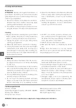
ATTENTION! The appliance must be installed on
the solid surfaces like concrete, wood or metal etc.
Important: Ensure that the supply cables is well
mounted and that it does not come into contact
with reflector of the heater or that does not trail
into heated area, the supply cable can be fixed to
the metal mounting bracket behind heater with
plastic zip ties.
1. This heater should be installed by a competent
person, i.e. a qualified electrician.
2. Always disconnected the heater from the elec-
tricity supply and allow it to cool before instal-
lation.
3. For ceiling mounting, the lowest part of the heat-
er must be located at or above a minimum height
of 2.4m from ground level, so that the heater can
not be touched when in operation.
4. For ceiling mounting, there must be a 2.4m dis-
tance from your appliance to the ground.
5. When installed to the ceiling, there must be a
distance of 0.5m between corners and the ap-
pliance.
6. The distance of your appliance from the living
beings is to be min 1m.
7. The distance from the front side of the heater to
materials such as wood, carton, cloth etc., must
be min 1m.
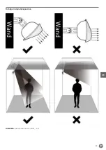
8. When mounting to a ceiling, do not position the
heater at an angle more than 90°and less than
45°.
9. The supply cable must be at the lower end of the
heater if the heater is installed at an angle or
vertically.
10. Keep the supply cord away from the body of the
heater which will get hot during use.
11. Do not install the heater on an inflammable
surface.
12. Observe the minimum safe distance between
the heater body and the inflammable surfaces
when mounted.
13. The heater should always have a minimum
clearance of 0.5m from a ceiling and adjacent
walls.
14. If the heater is to be used outside, a weather-
proof outlet is recommended.
15. Before drilling ensure that there are no wires
or water pipes in the area where the heater is
to be installed.
16. The heater must be installed on the mounting
brackets provided.
17. Fasten the brackets securely to the mounting
surface and the backside of the heater using
the nuts and screws supplied.
18. Fasten the heater securely on the brackets us-
ing the nuts and bolts supplied.
19. The brackets can be used to adjust the direction
of the heater, adjust the heater angle by loosen-
ing the two bolts on the wall mounting bracket,
tighten the bolts again when the desired angle
is reached.
Summary of Contents for BOLA 272428
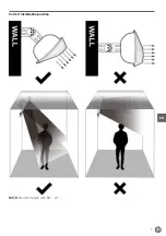
Page 7: ...7 EN Correct installation position NOTE Mounted angle with 30 45...
Page 19: ...19 DE Richtige Installationsposition Wand Wand HINWEIS Aufstellwinkel mit 30 45...
Page 30: ...30 NL Correcte installatiepositie Muur Muur OPMERKING Gemonteerde hoek met 30 45...
Page 52: ...52 FR Position d installation correcte Mur Mur NOTE Angle de montage avec 30 45...
Page 63: ...63 IT Posizione di installazione corretta Parete Parete NOTA Angolo di montaggio 30 45...
Page 74: ...74 RO Pozi ia corect de instalare Perete Perete NOT Instalare n unghi de 30 45...
Page 81: ...81 RU Hendi...
Page 82: ...82 RU 3 0 9...
Page 83: ...83 RU 200 C 10...
Page 84: ...84 RU I HENDI BOLA...
Page 85: ...85 RU 19 7 2 4 1 2 3 2 4 4 2 4 5 0 5 6 1 7 1 8 90 45 9 10 11 12 13 0 5 14 15 16 17 18 19...
Page 86: ...86 RU 30 45...
Page 87: ...87 RU 3 0 9...
Page 88: ...88 RU 1 2 3 4 1 4 2 M6 60 4 3 6 2 4 6 1 2 5 M6 12 2...
Page 90: ...90 RU 2 1 2 1 2 3 1 2 3 1 1 L1 2 3 4...
Page 91: ...91 RU 1 1 2 3 4 1 2 3 4 5 6 1 2 3 4 5 6 7...
Page 92: ...92 RU 272428 220 240 50 60 2500 I IP55 900x100x 174 3...
Page 93: ...93 GR Hendi...
Page 94: ...94 GR 3 0 9 m...
Page 95: ...95 GR 200 C 10...
Page 97: ...97 GR 30 45...
Page 98: ...98 GR 3 0 9...
Page 99: ...99 GR 1 2 3 4 1 L 4 2 M 6 mm 60 mm 4 3 M 6 mm 2 4 6mm 1 mm 2 5 M 6 mm 12 mm 2...
Page 100: ...100 GR 0 5 0 5 0 5 0 5 2 4 2 4 90 45 2 4 m 1 2 L1 L2 L3 L4 1 2 3 4 L1 L4 2 3 5 0 24 0H 2 3...
Page 101: ...101 GR 2 AAA 1 2 1 2 3 1 2 3 E1 1 L1 2 3 4...


