Alignment & Adjustments
32
17730-241
AR2
™
40K • 46K
6 . Verify all suspension components are in good condition . Repair or replace any worn or damaged
suspension components before proceeding with the alignment process .
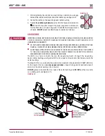
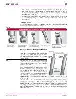
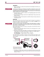
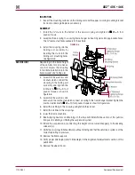
7 . Ensure all drive axle tires are the same size .
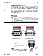
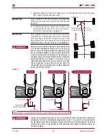
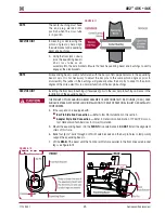
8 . Measure from the outside of the frame rail to the rim flange of the inner tire . Record the mea-
surement
A
and
B
, see Figure 7-6 .
9 . Measure the same distance on the opposite side of the same axle . Record the measurement
C
and
D
, see Figure 7-6 .
10 . Verify the lateral alignment is within the vehicle manufacturer’s specifications . Adding or remov-
ing shims that are located between the transverse torque rod and frame rail will normally correct
the lateral alignment .
■
A general rule of thumb is to use a shim with a thickness that is half of the difference
between the two measurements
ExAMpLE
If the lateral alignment is out of specification by ¼" (6 mm), remove or install a
1
⁄
8
" (3 mm) shim
between the transverse torque rod and frame rail as needed .
NOTE
Hendrickson recommends the use of Grade 8 bolts and Grade C locknuts be used for all torque
rod attachments .
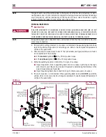
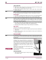
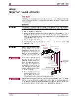
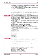
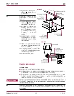
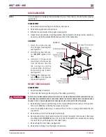
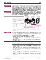
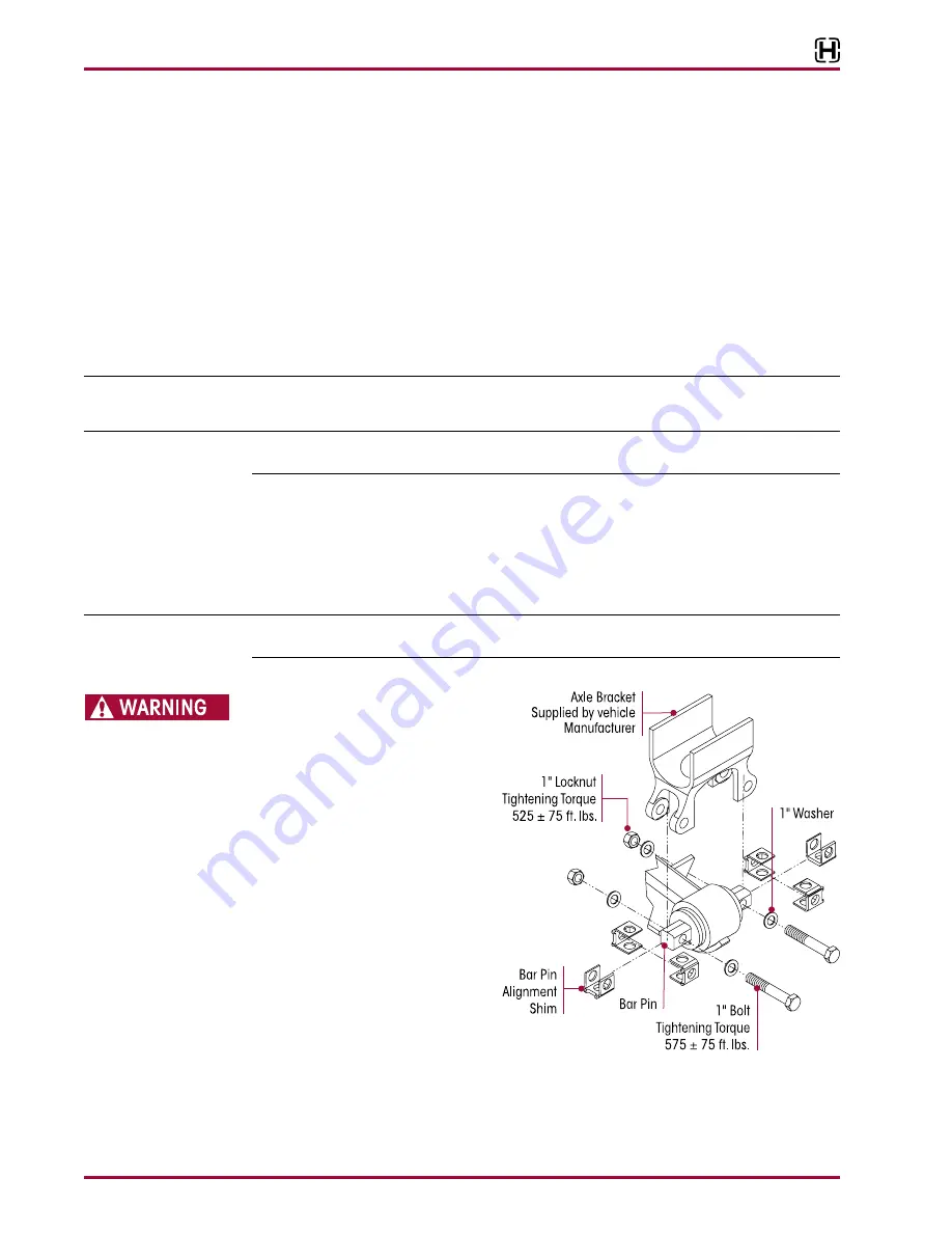
BAR pIN wITH SHIMS ALIgNMENT
The alignment feature consists of specially designed, tight tolerance steel shims which fill the
3
⁄
8
"
(9 .5 mm) total gap between the bushing’s bar pin and the axle bracket legs . The gap must be
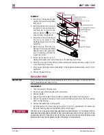
filled by placing the shims on the bushing assembly in one of the positions shown in Figure 7-7
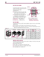
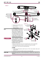
or 7-9 . Hendrickson has three (3) shim design options for alignment, see Figure 7-10 .
NOTE
Drive axle alignment with suspensions equipped with adapter style beam or non-shim style end
connections
ARE NOT
adjustable .
FIguRE 7‑7
A BAR PIN SHIM MUST BE INSTALLED
AT EACH BOLT LOCATION . THE SAME
PART NUMBER SHIM IN THE SAME
ORIENTATION MUST BE USED AT BOTH
BOLT LOCATIONS ON ANY ONE (1)
END BUSHING . DO NOT INSTALL OR
STACK MORE THAN ONE (1) SHIM AT
EACH BOLT LOCATION . USE GENUINE
HENDRICKSON BAR PIN SHIMS, DO NOT
USE STANDARD WASHERS . FAILURE TO
FOLLOW THESE WARNINGS MAY RESULT
IN IMPROPER VEHICLE ALIGNMENT,
FRACTURE OF THE AXLE BRACKET OR
BAR PIN WHICH COULD RESULT IN
THE ADVERSE VEHICLE HANDLING
AND POSSIBLE PERSONAL INjURY OR
PROPERTY DAMAGE .
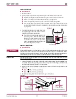
ALIgNMENT AdjuSTMENT
pROCEduRE
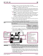
Computerized alignment equipment is the preferred method of measuring alignment . To calculate
the shim thickness required, the target offset must be converted to thrust angle, see alignment
equipment manufacturer for procedures . If alignment of the drive axles is required, as determined
by an alignment inspection procedure, the following Steps will need to be performed .

