17730-241
41
Component Replacement
AR2
™
40K • 46K
INSpECTION
1 . Inspect the mounting surfaces on the trailing arm and the upper air spring mounting bracket
for cracks or damage . Replace as necessary .
ASSEMBLY
1 . Install the ½" studs in the bottom of the new air spring and tighten to
25 ± 5 foot
pounds torque .
2 . Assemble the air spring to air spring frame hanger by inserting studs into appropriate holes .
The ¾" combo stud faces outboard of the vehicle .
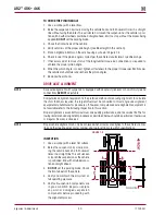
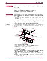
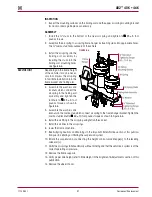
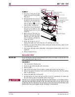
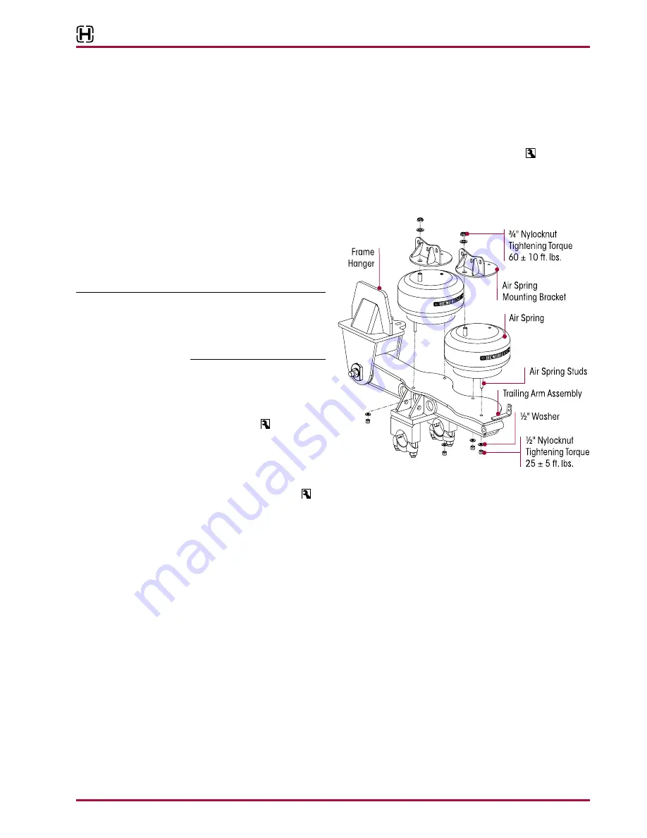
FIguRE 8‑6
3 . Install the air spring into the
trailing arm assembly by
inserting the studs into the
trailing arm mounting holes,
see Figure 8-6 .
SERVICE HINT
Depending on the frame height
of the vehicle it may be neces-
sary to compress the air spring
to facilitate installation into the
frame bracket and trailing arm .
4 . Assemble the washers and
locknuts which connect the
air spring to the trailing arm
assembly and tighten the
locknuts to
25 ± 5 foot
pounds torque as shown in
Figure 8-6 .
5 . Assemble the washers and
locknuts on the combo stud which connect air spring to the frame hanger bracket . Tighten the
combo stud locknut to
60 ± 10 foot pounds torque as shown in Figure 8-6 .
6 . Install the air fitting to the air spring using Teflon thread seal .
7 . Install the air lines to the air springs .
8 . Lower the frame of vehicle .
9 . See Air Spring Cautions and Warnings in the Important Safety Notice section of this publica-
tion prior to deflating or inflating the suspension system .
10 . Inflate the suspension by connecting the height control valve linkage(s) to the leveling
valve arm(s) .
11 . Verify the air springs inflate uniformly without binding and that the vehicle air system is at the
correct operating air pressure .
12 . Remove the frame supports .
13 . Verify proper ride height, refer to Ride Height in the Alignment & Adjustments section of this
publication .
14 . Remove the wheel chocks .

