17730-241
43
Component Replacement
AR2
™
40K • 46K
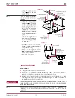
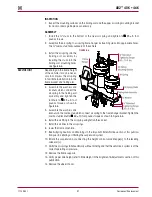
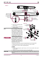
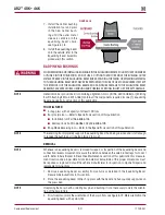
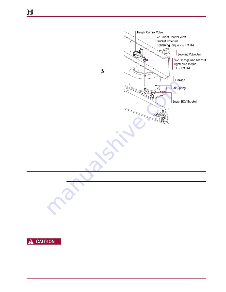
FIguRE 8‑8
ASSEMBLY
1 . Install the air fittings into the new
height control valve using Teflon
thread seal .
2 . Install the height control valve to
the frame mounting bracket by
attaching the ¼" washers and
locknuts . Tighten to
9 ± 1 foot
pounds torque, see Figure 8-8 .
3 . Install the air lines to the height
control valve . Refer to the
Plumbing Diagram section of this
publication .
4 . See Air Spring Cautions and
Warnings in the Important Safety
Notice section of this publication
prior to deflating or inflating the
suspension system .
5 . Inflate the suspension by con-
necting the height control valve linkage(s) to the leveling valve arm(s) .
6 . Verify the air springs inflate uniformly without binding and that the vehicle air system is at the
correct operating air pressure .
7 . Verify proper ride height, refer to Ride Height in the Alignment & Adjustments section of this
publication .
8 . Remove the wheel chocks .
EquALIzINg BEAM
SERVICE HINT
It is recommended to remove both equalizing beams and the cross tube as a group even if only
one (1) equalizing beam needs service .
dISASSEMBLY
1 . Chock the wheels of the steer axle .
2 . Raise and support the drive axles with safety stands .
3 . Remove the tires .
4 . Support the pinion angle of the drive axles to prevent axle movement during service .
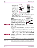
5 . Remove the saddle cap fasteners from both inboard and outboard sides of both equalizing
beam’s center bushings .
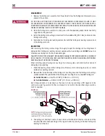
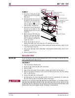
6 . Remove the saddle caps, see Figure 8-9 .
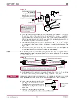
7 . Raise the vehicle’s frame just enough to create a ½" (13 mm) gap between the saddles and
the center bushings . Support the vehicle’s frame at this height .
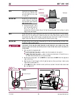
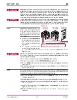
THE WEIGHT OF THE EQUALIZING BEAM ASSEMBLY IS APPROXIMATELY 155 POUNDS . PRIOR TO
REMOVING THE BEAM END FASTENERS FROM THE EQUALIZING BEAM, SUPPORT THE END OF THE
EQUALIZING BEAM TO PREVENT FROM DROPPING . CARE SHOULD BE TAKEN AT REMOVAL AND
INSTALLATION TO PREVENT PERSONAL INjURY OR DAMAGE TO COMPONENTS .

