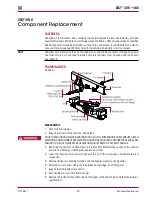
Component Replacement
44
17730-241
AR2
™
40K • 46K
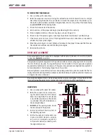
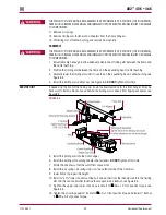
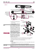
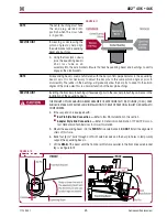
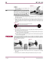
FIguRE 8‑9
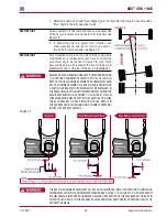
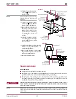
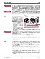
FIguRE 8‑10
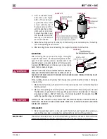
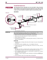
8 . Support both equalizing beams
with a floor jack .
9 . Remove and discard beam end
attaching fasteners .
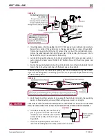
NOTE
Prior to disassembly of the equalizing
beam bar pin fasteners, note the orien-
tation of the bar pin alignment shims,
see Figure 8-10 . It is required that the
bar pin alignment shims are installed
in the same orientation and location
as removed to preserve the existing
vehicle alignment . Improper vehicle
alignment can increase tire wear .
PRIOR TO REMOVING BOTH EQUALIZING
BEAMS, SUPPORT THE PINION OF
EACH DRIVE AXLE . FAILURE TO DO SO
CAN RESULT IN PERSONAL INjURY OR
ALLOW THE AXLES TO SHIFT MAKING
REASSEMBLY MORE DIFFICULT .
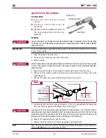
10 . Slowly lower the floor jacks and remove the equalizing beams from the axle brackets .
11 . Slide the equalizing beams off the cross tube and out from under the vehicle .
12 . Remove the floor jacks from under the equalizing beams .
ASSEMBLY
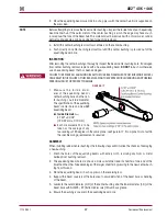
1 . Position the equalizing beams under the axles with a floor jack under the center of each
equalizing beam .
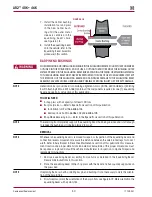
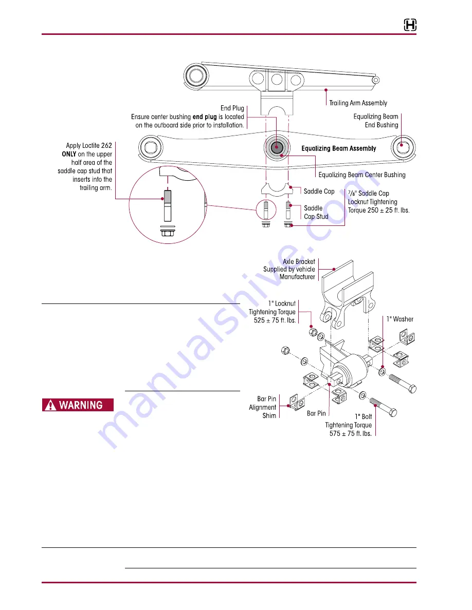
2 . Install the cross tube into the center bushing of each equalizing beam .
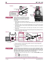
SERVICE HINT
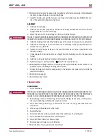
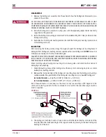
Ensure the equalizing beam’s center bushing end plug is located on the outboard side, see
Figure 8-11 .

