17730-241
45
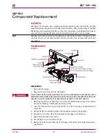
Component Replacement
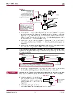
AR2
™
40K • 46K
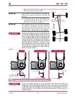
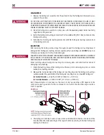
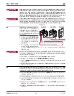
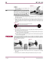
FIguRE 8‑11
NOTE
The center bushing must have
the end plug welded into
position when the cross tube
is in position .
SERVICE HINT
Increasing or decreasing the
pinion angle may help align
the axle bracket and equalizing
beam end bushings .
3 . Using the floor jacks, slowly
raise the equalizing beams
a n d c ro s s t u b e a s a n
assembly into the axle brackets . Ensure that each equalizing beam end bushings correctly
engages the axle brackets .
NOTE
All equalizing beams are manufactured with the bar pin flats perpendicular to the equalizing
beam’s axis . It is not necessary to adjust the bar pins to the same pinion angle as prior to
disassembly . The rubber in the bushings will gradually allow the bar pins to adapt to the pinion
angles of the drive axles . This is a normal function of the bar pin bushings .
SERVICE HINT
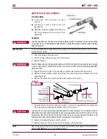
Installing the front bar pin bushings (if equipped) prior to the rear bar pin bushings will ease in the
installation of the equalizing beam .
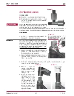
THE WEIGHT OF THE EQUALIZING BEAM ASSEMBLY IS APPROXIMATELY 155 POUNDS (70 KG) . CARE
SHOULD BE TAKEN AT REMOVAL AND INSTALLATION TO PREVENT PERSONAL INjURY OR DAMAGE TO
COMPONENTS .
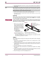
4 . If the suspension is equipped with:
■
Bar pin Style End Connection —
Refer to Bar Pin Installation in this section
■
Adapter Style End Connection —
Refer to Hendrickson Publication 17730-190 or con-
tact Hendrickson Tech Services for more information
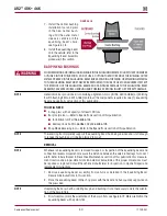
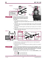
5 . Mount the equalizing beam into the
FRONT
drive axle brackets .
dO NOT
install the alignment
shims at this time .
6 . Slide four (4) ¾" bolts through both front axle brackets and the bar pin holes to temporarily
support the equalizing beams .
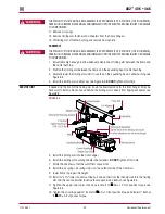
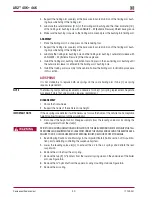
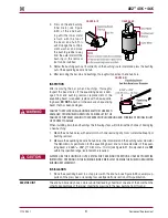
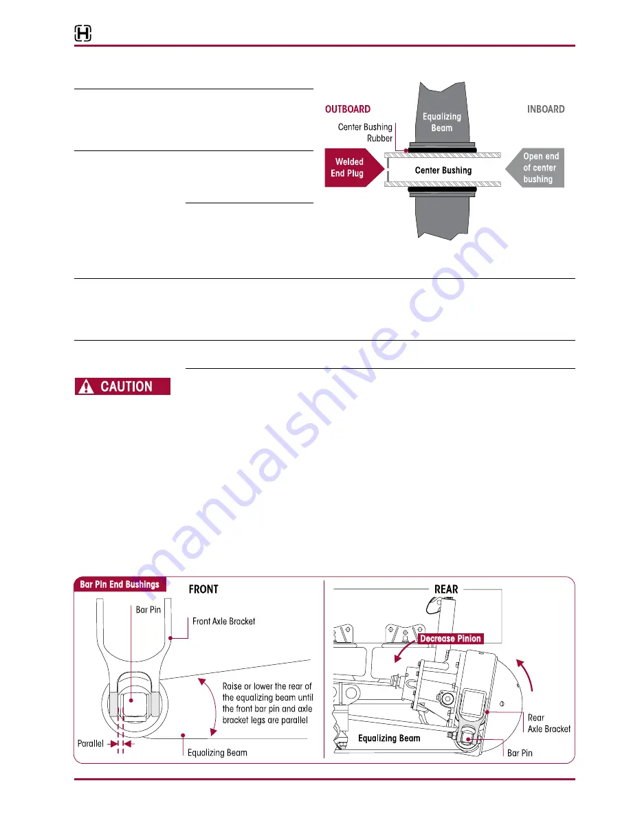
7 . Lift the
REAR
of the beam until the front bar pin flats are parallel to the front drive axle bracket
legs, see Figure 8-12 .
FIguRE 8‑12


